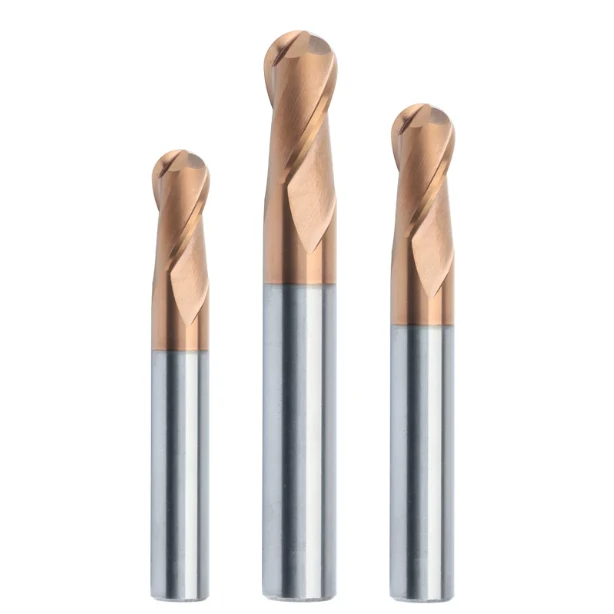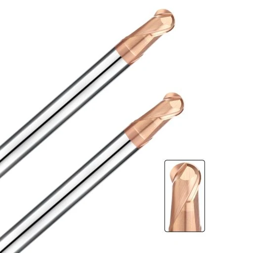

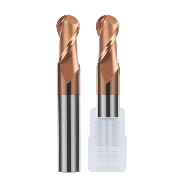
A process supervisor at a precision mold shop in Ohio recently sent us several broken R3 coated cutters. Their inspection report showed that while finish-milling a hardened H13 mold cavity (HRC 60), the tools suffered severe center-chipping and flank sintering in under 15 minutes.
This is not an isolated incident. Over the past decade of frontline technical support and trial-machining projects, we have seen this exact failure pattern repeatedly. Veteran machinists who handle conventional alloy steels effortlessly often hit a wall once material hardness crosses HRC 55.
When cutting hardened steel, a ball nose end mill does not remove metal through raw sharpness alone. Because of its spherical tip geometry, effective surface speed drops to zero right at the center. If you misread the core ball nose cutter cutting principle, the tool tip plows and compresses the steel instead of shearing it, generating extreme heat that destroys the coating and carbide substrate.
From our R&D lab tests and on-site troubleshooting, running a ball nose end mill for HRC62 steel requires calibrating tool geometry, overhang rigidity, tilt angle, and micron-level edge honing as one system. When finish-milling steep mold walls, have you ever dialed in the exact spindle RPM, only to watch the center tip flatten out prematurely or leave ugly chatter marks?
The Core Ball Nose Cutter Cutting Principle in Hardened Materials
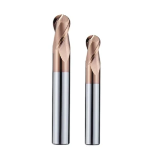
During on-site troubleshooting across North American and European mold shops, we routinely see operators crank up the spindle speed on ball nose cutters just to chase a better finish. However, the contact dynamics along a spherical cutting edge shift continuously from the outer diameter to the center tip, which is the foundation of the ball nose cutter cutting principle.
When machining hardened mold steel above HRC58, you cannot rely blindly on default CAM speed and feed tables. You have to control the shear angle and chip thickness at the exact point of engagement. Without clean shearing action, chips fail to evacuate heat and instead smear into a work-hardened layer that rapidly destroys the cutting edge.
Why Zero-Surface-Speed at the Center Tip Destroys Tool Life
A German automotive mold maker once sent us a batch of failed R4 carbide ball nose cutters used to finish the bottom radii of hardened D2 (1.2379) inserts. Tool life consistently stalled at 20 minutes. Under a high-magnification toolmaker’s microscope, we found the outer peripheral flutes looked brand new, while the center chisel edge showed severe crater wear and micro-chipping.
When a ball nose cutter engages a flat or shallow surface vertically at a 0° tilt, the cutting radius shrinks to zero at the exact pole. Inside this zero-velocity dead zone, ball nose milling stops shearing metal and starts plowing hardened steel under extreme compressive stress. The resulting frictional spike softens the PVD coating within seconds and tears out the underlying carbide grains.
Optimizing Tilt Angle and Effective Diameter in the Ball Nose End Milling Process
To solve that German shop’s bottleneck, we ran a series of 5-axis simultaneous test cuts in our lab by tilting the spindle 15° to 25° relative to the surface normal. Tilting the tool lifts the dead-zone chisel edge completely out of the cut, forcing the higher-speed curved side flutes to do the work. This is our go-to adjustment when optimizing any ball nose end milling process.
Once you tilt the tool, you must recalculate spindle RPM using the effective cutting diameter (Deff) rather than the nominal tool diameter. At a 20° tilt, Deff drops to roughly half the nominal size, meaning you must boost RPM accordingly so the flutes slice cleanly instead of rubbing. If your shop runs 3-axis machines without spindle tilt, avoid vertical plunging—use helical entry and keep finishing stock under 0.05 mm to protect the center tip.
Engineering the Ball Nose Cutting Edge for Mold Steel and HRC62 Steel
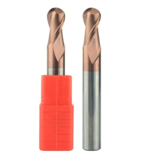
In our five-axis grinding shop, customers frequently show us blueprints for identical R2 ball nose cutters and ask why one finishes an entire mold core while another chips in 30 minutes. The difference rarely comes down to the carbide grade itself; instead, it is hidden within the microscopic geometry of the ball nose cutting edge.
Designing an edge for hardened mold steel is a strict trade-off between sharpness and edge strength. If the flute is ground razor-sharp, it fractures on contact with hard steel, whereas an overly blunted edge spikes radial cutting forces and deflects the tool out of tolerance.
Negative Rake Geometry and Edge Preparation for a Ball Nose End Mill for HRC62 Steel
Through hundreds of destructive life tests on hardened H13 and D2 steel at HRC62, we proved that sharp, positive-rake edges fail in under eight minutes due to jagged micro-chipping. When engineering a ball nose end mill for HRC62 steel, we grind an effective negative rake angle between -6° and -12° to keep the carbide substrate under compression rather than tension during impact.
Negative rake geometry must also be paired with tight, micron-level edge honing. On our production lines, we hone HRC62 cutters to a radius between 0.005 mm and 0.012 mm—eliminating grinding micro-burrs without generating excessive plowing heat—so you can hold tight tolerances across hardened mold cores.
Chip Evacuation and Flute Design in a Ball End Milling Cutter
Many buyers assume deeper flutes always deliver better performance, but that logic fails when clearing corners in deep mold cavities. While troubleshooting chatter on deep-cavity S136 steel for a North American medical mold maker, we found their standard 2-flute cutters had a core diameter of just 52%, causing severe elastic deflection whenever corner stock fluctuated.
To fix this, we redesigned the ball end milling cutter by sacrificing excess flute depth to boost the core diameter above 65%, while shifting to a 4- or 6-flute layout for shallow finishing. Hardened steel finishing produces fine, needle-like dust rather than thick curls, so a thick core with polished U-flutes clears chips cleanly under air blast while resisting radial corner loads.
Mastering Ball Nose End Mill for 3D Surface Finishing Without Chatter
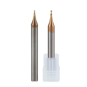
While roughing focuses on metal removal rates, the surface finish off the machine determines how many hours your bench hands spend polishing. When optimizing processes for European and North American mold shops, we often see teams struggle to break below Ra 0.2 μm because their ball nose end mill for 3D surface finishing does not match the part’s changing surface angles.
Once chatter or witness lines appear on hardened steel, manual stoning eats up shop hours and risks ruining precision parting lines. Based on our trial-machining data, simply slowing down the feed rate rarely solves this; you have to combine slope-based toolpath splitting with rigid overhang control.
Step-Over, Scallop Height, and Toolpath Strategy in Ball Nose Milling
A North American manufacturer of artificial joint molds once came to us with stepped chatter marks on sidewalls steeper than 60° when finishing with an R1.5 cutter. Reviewing their CAM file showed the programmer used a single parallel raster toolpath across the entire part, causing massive chip-load spikes during ball nose milling on steep walls.
We fixed the issue by splitting the geometry at a 45° slope threshold into steep and shallow zones. We ran constant-Z waterline passes on steep walls to keep step-down consistent, and switched to 3D-offset paths with a 3% to 5% step-over on shallow areas to cap scallop height under 0.002 mm—adding ten minutes of programming to save hours of bench polishing.
Managing Deflection and Overhang on Deep Cavity Mold Steel
Once a tool’s length-to-diameter (L/D) ratio exceeds 5:1 in deep cavities, it acts like a cantilever beam and bends under cutting loads, triggering high-frequency chatter. In a recent project for an automotive lighting mold shop, standard straight-shank cutters running at 7xD overhang left tapered walls and heavy micro-chipping along the ribs.
Simply upsizing the shank causes wall collisions in deep pockets, so we engineered an extended-shank tool with a 1.5° to 3° tapered neck relief to push maximum rigidity closer to the tip. When grinding each ball nose end mill for mold steel, we also apply variable helix angles and unequal flute spacing to disrupt harmonic frequencies and stop micro-vibrations before they start.
Real-World Ball Nose End Mill Speeds and Feeds for Hardened Steel
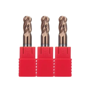
During on-site technical support across North American mold shops, we often see machinists pull parameters straight from catalog backs—scorching expensive coated cutters on the first pass. Catalog charts are built under ideal, rigid lab conditions, whereas real-world spindle runout, overhang, and uneven stock dictate safe ball nose end mill speeds and feeds.
In our test-cutting lab, we never tune hardened steel parameters just to max out cycle speed; our goal is to let the chips carry away over 80% of the cutting heat. Dark brown or blue chips mean you have crossed the coating’s thermal limit, while silver-white, needle-like chips confirm the tool is shearing cleanly.
Cutting Parameters for Pre-Hardened vs. Fully Hardened Ball Nose End Mill for Mold Steel
For a standard R3 (6 mm) 4-flute solid carbide cutter on pre-hardened P20 or NAK80 (HRC45–52), we run cutting speeds (Vc) of 160–200 m/min and a feed per tooth (fz) of 0.04–0.06 mm/z. On fully hardened H13 or D2 (HRC58–62), we drop Vc to 90–120 m/min, tighten fz to 0.02–0.035 mm/z, and cap axial depth of cut (ap) at 0.05–0.10 mm.
When calculating RPM for a ball nose end mill for mold steel, never plug the nominal tool diameter into your formula. In shallow 3D finishing, the effective cutting diameter is only 30% to 50% of the nominal size, so you must multiply your theoretical RPM by 1.4x to 1.8x to maintain proper surface speed and prevent abrasive rubbing.
Dry Air Blast vs. MQL: Coolant Mistakes We Fix for CNC Shops
Running flood coolant during high-speed hardened steel finishing is a death sentence for carbide tools. At a Michigan stamping die shop, operators complained of flaking coatings because they were blasting a 900°C cutting zone with cold water-soluble coolant—triggering violent thermal shock cracks within ten minutes.
In our lab and customer setups, ball nose milling above HRC55 requires shutting off flood coolant completely and using a 5–6 bar dry air blast to clear fine chips and stabilize heat. For sticky high-alloy steels, add a trace of vegetable-based MQL oil mist into the air stream—just aim the nozzle directly at the tip to cut friction without causing smoke or localized overheating.
Inside Our Ball Nose Milling Cutters Factory: How We Control Runout and Coating
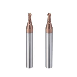
Once you dial in negative rake angles, variable helix flutes, and effective diameter RPM, final mold surface finish comes down to manufacturing consistency. As a specialized ball nose milling cutters factory, we have inspected countless returned tools where identical R2 ±0.005 mm specs delivered a 100% variance in HRC62 tool life due to geometric runout and coating instability.
In our grinding and coating departments, quality control is benchmarked against live machine dynamics rather than paper reports. Even if your holder runout is under 0.002 mm, a few microns of asymmetry across the ball radius turns a multi-flute finishing pass into a single-flute hammering cycle.
Sub-Micron Arc Grinding and Center Chisel Accuracy
If the radius profile deviation between two flutes exceeds 0.003 mm during hard finishing, one flute absorbs over 80% of the cutting load—leaving visible surface ripples and causing early chipping. To prevent this, our 5-axis CNC grinders use automated in-process laser probes to scan every arc and compensate for wheel wear in real time, holding contour accuracy within ±0.002 mm.
Centering the chisel edge at the very tip is equally critical and frequently overlooked by standard shops. Our quality engineers inspect every hardened-steel batch on a non-contact optical profiler to verify chisel over-center accuracy and S-curve smoothness, ensuring balanced force distribution upon workpiece entry.
Selecting AlCrSiN vs. TiSiN Coatings for Extreme Thermal Resistance
Instantaneous cutting temperatures in hardened steel often exceed 900°C, causing standard coatings to oxidize, soften, and weld to chips. Through in-house PVD coating trials on our ball nose end mill for HRC62 steel, we confirmed that high-aluminum AlCrSiN resists oxidation up to 1100°C—outperforming conventional TiSiN against crater wear in dry air-blast finishing.
Still, AlCrSiN is not a universal fix; for stickier pre-hardened mold steels around HRC50, TiSiN’s lower friction coefficient suppresses built-up edge (BUE) and clears chips more smoothly. We strictly cap coating thickness between 2.5 and 3.5 microns across all grades, because thicker layers artificially enlarge the edge hone radius and dull the micron-level sharpness needed for hard finishing.