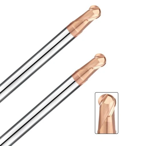

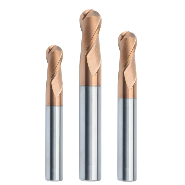
A long-standing German client of mine—who builds automotive light cover molds—sent over photos of a scrapped workpiece alongside SEM images of the cutter. The part was an S136 cavity hardened to HRC 62. After the final finishing pass, visible chatter and blue burn marks showed up along the curved transition zones, prompting the shop to waste two days recalibrating spindle thermal growth.
When we inspected the returned solid carbide ball nose end mill, the machine wasn’t the problem at all. The dead center of the ball tip—where surface speed drops to zero—had suffered severe micro-chipping and built-up edge (BUE), turning a clean cut into pure friction.
Over sixteen years of supporting machine shops across North America and Europe, we see this exact failure almost every month. Many programmers treat a ball nose milling cutter like a flat-end mill with a rounded tip, yet the physics governing 3D contour milling are completely different.
On complex free-form surfaces and deep cavities, your final Ra finish rarely depends on how expensive your 5-axis machine is. Instead, success hinges on controlling your effective cutting diameter via the ball nose radius, compensating for chip thinning, and running a true HRC65 ball nose end mill built for thermal shock resistance.
If you pick a tool straight out of a catalog without checking edge prep, neck rigidity, or contact-point linear speed, you risk burning a twelve-hour finishing cycle. You will either double your bench polishing hours or scrap the mold insert entirely.
Skipping textbook theory, we will use real shop-floor cutting data to break down how to run these tools in surface contour machining. Have you ever followed every catalog speed and feed to the letter, only to leave stubborn step-over lines across a critical parting surface?
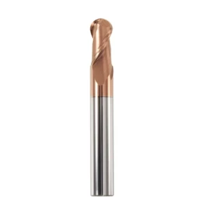
Understanding the Ball Nose Milling Cutter: Insights from the Shop Floor
If you have examined hundreds of worn tools on the shop floor, you know that surface ripples and edge chipping rarely stem from weak machine rigidity. Instead, they happen when programmers overlook the shifting force dynamics of a ball nose milling cutter. Unlike a flat end mill that splits loads between side and bottom flutes, a ball nose tool’s contact point constantly migrates along its hemispherical arc.
During on-site troubleshooting in the US and Europe, our first move is always checking the tip wear band under a loupe. Once you account for chip evacuation paths, core diameter distribution, and shifting effective diameters across changing slopes, you can eliminate over 80% of premature breakage right at the CAM programming stage.
Beyond Textbook Definitions: Why Tool Geometry Is Critical in Real-World Machining
A standard ball nose end mill definition simply describes a hemispherical cutter built for 3D surfaces, yet center-cutting geometry is what actually makes or breaks tight-tolerance parts. When we grind S-gash and center-cutting edges, leaving the central web too thick creates massive axial thrust during plunges or shallow passes. Chips get trapped, and localized heat spikes past the coating’s failure threshold in seconds.
Conversely, grinding an overly aggressive positive rake angle strips away vital edge support. In mold steels above HRC 58, a razor-thin edge micro-chips within ten minutes. We prioritize a core-to-diameter ratio above 0.65—even if it sacrifices some flute space—paired with controlled micro-edge honing to stabilize the cut in hard alloys.
How Ball Nose Radius Influences Tool Deflection and Chip Load
When programming deep mold corners, it is tempting to pick a ball nose radius that simply matches the smallest print fillet. However, that radius also dictates tool overhang rigidity and your true effective cutting speed. When your axial depth of cut (ap) is much smaller than the radius, the actual engaged diameter shrinks dramatically—cutting your real surface speed in half and compressing chips into a rubbing action.
While machining a 120 mm deep die-casting runner system, we had to make a strategic trade-off. Rather than pushing a skinny, long-reach cutter that would deflect badly, we ran a larger radius during roughing and semi-finishing to maintain proper chip load. We only switched to a smaller ball radius end mill with a constant-engagement toolpath for final fillet cleanup, keeping cavity tolerances dead-on.
Solid Carbide Ball Nose End Mills vs Indexable Cutters: Lessons from High-Precision Runs
Shop estimators often debate between a solid carbide ball nose end mill and an indexable insert cutter for large 3D finishing runs. We learned a costly lesson during a 72-hour medical mold run: using a 16 mm two-flute indexable cutter to save on insert costs introduced micron-level pocket runout. Uneven flute loading left visible light-and-dark bands across the core, costing our bench hands an extra day of hand polishing.
Switching that operation to single-piece solid carbide solved the issue immediately. Despite a higher upfront tool price, superior grinding concentricity and four-flute load sharing boosted feed rates by 35% while holding profile accuracy within 0.008 mm. Use indexable tools for heavy roughing above 20 mm, but trust solid carbide whenever long-overhang vibration or mirror finishes are on the line.
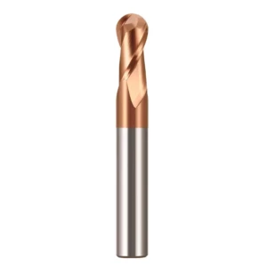
Core Applications of Ball Nose End Mills in 3D Contour Milling and Surface Contour Machining
Many planners assume ball nose end mill applications simply mean running a rounded cutter over every curved feature. In our work optimizing cycle times for aerospace and mold-making shops across North America and Europe, blanket usage is actually the main driver of sluggish spindle efficiency. A ball nose tool earns its keep on free-form surfaces with continuously changing slopes, multi-axis fillet cleanup, and radii where sharp corners would cause stress fractures.
You must evaluate surface curvature and wall rigidity before choosing your finishing cutter. Use a ball nose tool when maintaining a uniform scallop height across steep-to-shallow contours, or switch to a bull nose cutter to boost feed rates on flatter floors. The shop-floor challenges below are the exact bottlenecks we tackle when helping clients shave over 20% off their cycle times.
Solving Residual Height and Cusp Mark Issues in Complex Surface Contour Machining
During surface contour machining on automotive trim or optical reflector molds, abrupt transitions from shallow to steep slopes often leave glaring, wavy marks. Most programmers react by tightening the step-over, which doubles runtime and rubs the cutting edge dull—creating even deeper cusp lines.
While commissioning a job for a North American optical mold shop, we scrapped simple parallel passes in favor of a constant-scallop toolpath capped at 0.002 mm. Adding a 15-degree overlap zone where steep walls meet flat floors eliminated slope-change chatter and removed the need for hand sanding that distorts optical surfaces.
Optimizing Toolpaths and Preventing Interference in Deep-Cavity 3D Contour Milling
Once cavity depth exceeds six times the tool diameter, 3D contour milling stops being about surface finish and becomes a battle against chatter and holder collisions. We regularly see shops hang a standard straight-shank tool 100 mm out of a collet, only for radial runout to gouge a $30,000 mold insert within two minutes.
For deep cavities, we grind custom tools with tapered or relieved necks to maximize cross-sectional rigidity while maintaining wall clearance. We also ban vertical plunging in favor of helical ramping and unidirectional climb milling, keeping radial engagement (ae) constant so the cutter never overloads in tight corners.
Choosing the Right Ball-Nose End Mill for Impellers, Turbines, and Medical Components
When cutting aero-engine blisks, turbine blades, or titanium orthopedic implants, selecting a ball radius end mill shifts from metal removal rates to controlling heat and residual stress. Alloys like Inconel 718 and Ti-6Al-4V trap heat at the cut zone, meaning a tiny radius with a negative rake will quickly warp thin blades or cause surface micro-cracking.
For Swiss and German medical clients, we specify tapered, variable-helix tools with high positive rake angles to shear thin-walled impeller channels cleanly. Conversely, when finishing abrasive cobalt-chrome artificial joints, we dial back edge sharpness slightly to hold a ±0.003 mm profile tolerance for a single-pass mirror finish.
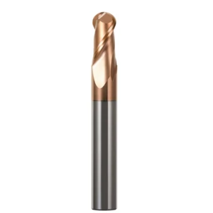
Machining Hardened Mold Steels: Field Data Using Ball Nose End Mills for HRC65 Applications
Once mold steel exceeds HRC 58 after heat treatment, high-speed dry milling plays by entirely different rules. Across our lab tests and partner shops in the US and Europe, cutting zones in HRC 62–65 steel routinely hit 900°C—turning standard soft-steel feeds into instant thermal cracking and edge chipping.
Tracking HRC65 ball nose end mill performance across more than forty precision mold shops proved one clear rule: tool life does not come from aggressive depths of cut. Instead, survival depends on substrate transverse rupture strength, ultra-fine carbide grain structure, and thermal-barrier coating stability under high-frequency impact.
Why Standard Cutters Fail: Selecting a Ball Nose End Mill for Hardened Steel
Toolmakers used to cutting pre-hardened P20 often grab general-purpose cutters with high rake angles and deep flutes, only to shatter the tip within five minutes on HRC 60+ steel. Thin, aggressive edges simply lack the backing needed to survive the massive compressive loads of hardened alloys, resulting in immediate brittle spalling.
When specifying a ball nose end mill for hardened steel, we mandate a reinforced negative-rake edge ground from sub-micron (under 0.2 μm) tungsten carbide. While a negative rake bumps cutting forces by roughly 15% and requires a rigid spindle, it converts destructive tensile stress into compressive stress that keeps the edge intact.
The Secrets Behind the Performance of Our HRC65 Ball Nose End Mills: Coating and Edge Preparation
Why do some HRC 65 cutters lose their temper in two hours while others run steady for eight? In our grinding facility, longevity comes down to pre-coat micro-edge preparation and heat-resistant nanolayer coatings, because grinding leaves microscopic saw-tooth burrs that cause fresh coatings to flake off on contact.
Before depositing AlCrSiN or multilayer AlTiSiN coatings on our HRC65 ball nose end mill line, we use nylon brushes and micro-blasting to hone a 3 to 5 μm edge radius. Although honed tools sound slightly duller on initial entry, removing edge stress risers lets the self-lubricating oxide layer shed heat straight into the chips.
Real-World Case Study: Eliminating Premature Tool Wear in H13 and S136 Mold Cavity Machining
Late last year, a North American medical packaging moldmaker contacted us because they were burning through cutters every two cavities while finishing HRC 61 S136 inserts. Reviewing their setup revealed the exact mistake: they were running flood coolant at low spindle speeds to prevent heat buildup.
Flooding a red-hot carbide tip causes severe thermal shock, creating a web of micro-cracks that destroys the edge. We had them shut off the coolant, switch to dry air blast, push an R2 cutter to 160 m/min, and lock step-over (ae) at 0.06 mm and depth (ap) at 0.08 mm—finishing all 12 cavities on one tool with under 0.05 mm flank wear and zero hand polishing.
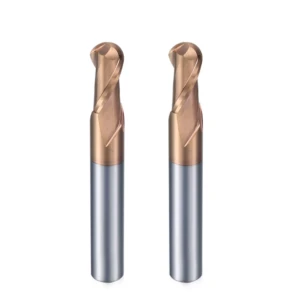
Common Shop Floor Mistakes When Using Ball Nose End Mills (And How to Resolve Them)
During process audits across North American and European mold shops, we see a telling pattern: a ball nose milling cutter fails early on one machine, yet runs flawlessly on another using identical speeds and feeds. This proves that tool geometry or coating is rarely the sole culprit behind poor surface finish. Instead, premature failure usually stems from shop-floor toolholding setups, CAM strategies, and misjudging physical cutting limits.
Following catalog speeds blindly without accounting for dynamic machine rigidity or shifting contact points will snap even top-tier carbide tools. The two operational mistakes below account for over 70% of the troubleshooting calls we have handled over the past sixteen years.
The “Zero Surface Speed” Trap at the Tip of the Ball Nose Radius
When programming 3-axis machines for shallow contours or flat parting lines, plunging straight down drops the cutter right into its worst physical blind spot. At the exact center of the ball nose radius, surface speed equals zero—meaning the tool smashes and plows metal under massive axial load rather than shearing it cleanly. This intense friction spikes localized heat, causing built-up edge (BUE) or snapping off the microscopic carbide tip.
To stop surface tearing on shallow 3-axis geometries, ditch parallel back-and-forth passes for contour-offset paths that spiral inward from the sidewalls. This forces the higher-speed radius flank to do the cutting. On 5-axis machines, tilt the spindle to a fixed 10- to 15-degree lead angle to keep the dead center completely out of the cut, boosting tool life and surface roughness (RaR_a) immediately.
Runout, Tool Holders, and Overhang: Hidden Killers of Surface Finish
When holding 0.005 mm tolerances on mold finishing, many operators buy precision cutters only to clamp them in worn-out standard ER collet chucks. If radial runout exceeds 0.01 mm, chip load shifts onto a single flute—dulling that edge early while leaving dense chatter marks across your cavity walls.
Our shop-floor rule is non-negotiable: whenever running a solid carbide ball nose end mill under 6 mm in diameter, or reaching past a 4xD overhang, standard spring collets are off-limits. Switch to shrink-fit holders or precision hydraulic chucks to lock total tip runout below 0.003 mm. While shrink-fit units require an upfront heater investment, protecting a $30,000 mold insert during overnight lights-out runs pays for itself fast.
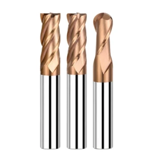
What to Look for in a Reliable Ball Nose End Mill Supplier
Even with dialed-in CAM toolpaths and sub-micron runout control, poor tool grinding precision will ruin your cut on the very first pass. Over sixteen years supplying precision shops in the US and Europe, we have seen countless automated lines suffer sudden finish degradation simply because a shop switched to a cheaper batch of cutters.
Choosing a ball nose end mill supplier who understands real-world machining means establishing a reliable baseline for your spindles. Instead of chasing the lowest catalog unit price, evaluate potential tooling partners against your toughest alloys and tightest print tolerances using these two benchmarks:
Batch Consistency and Grinding Tolerances: Quality Assurance Before Shipment
Nothing frustrates production engineers more than erratic tool life—where one cutter runs a full eight-hour shift, while the next identical tool snaps in two hours. This usually traces back to poor wheel-wear compensation on 5-axis grinders, mixed carbide grain batches, or drifting profile tolerances. In our grinding facility, we hold arc profile accuracy within ±0.003 mm and verify edge runout and core concentricity on optical tool presetters before shipping.
If you are sourcing tools for lights-out production, demand batch-specific laser inspection reports rather than relying on sample test data. Verify both the ball nose radius tolerance and edge-honing consistency, as a dependable manufacturer will back mass-production tolerance stability directly inside your technical agreement.
Customizing Neck Relief and Flute Geometry with Your Ball Nose End Mill Supplier
Standard catalog cutters are built as compromises for average jobs, leaving you short on rigidity or fighting wall interference in deep mold cavities and impeller channels. A capable ball nose end mill supplier with in-house grinding engineers should turn around custom relieved necks, tapered reinforcements, or alloy-specific flute geometries within 48 hours—rather than forcing you to compromise your process.
If you are battling early wear in hardened cavities, chatter on long-overhang cuts, or stubborn step-over lines on complex surfaces, send over your part prints, material hardness, and spindle specs. As fellow tooling engineers, we are glad to review your cutting forces, entry angles, and custom geometry options to solve the bottleneck together.