
That scrap report from an automotive headlamp mold trial still hangs on our lab wall. The workpiece was hardened H13 steel at 63.5 HRC. After burning through three batches of imported cutters, the customer saw severe micro-chipping in the corners at minute 12, leaving blending lines no amount of hand polishing could save.
Over 16 years of R&D and supporting mold shops across North America and Europe, we have seen this exact failure repeat itself. Many machinists push standard coated tools into hard milling, which only tanks spindle efficiency and drives up cost-per-part.
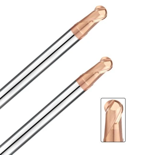
When milling 60 to 65 HRC steels like D2, S136, or M2, picking the right HRC65 ball nose end mill isn’t about blindly maxing out RPM. It requires matching tool geometry, ultra-fine carbide substrates, and cutting parameters. Miss one variable—whether deep-cavity rigidity or center-point protection—and your carbide ball nose cutter for hardened steel will fail prematurely.
In this guide, we skip textbook theory and share hard data from thousands of failure analyses and HRC65 ball nose end mill cutting parameters tests. We will cover 2-flute vs. 4-flute selection, coating heat limits, and how to boost HRC65 ball nose end mill tool life by over 40%.
If your shop still relies on frequent tool changes and hours of manual benching just to hold tolerances, have you calculated how much hidden profit is disappearing at the spindle?

Why Standard Carbide Ball End Mills Fail Within 15 Minutes on HRC65 Steel
Whenever we open a box of failed cutters returned from a mold shop, the root cause is usually obvious. Most operators try to force standard HRC55 general-purpose cutters through hardened tool steel. Under tight deadlines, they crank up RPM and drop feed rates to “rub” a smooth finish, instantly overheating the tool in the cut.
In hard milling, general-purpose tools and a dedicated HRC65 ball nose end mill operate in completely different thermal zones. Above 60 HRC, cutting zone temperatures spike past 900°C (1,650°F). Standard carbide loses its red hardness immediately, meaning a 15-minute failure isn’t a machine issue—the tool simply wasn’t engineered for these extreme loads.
What We Found in Returned Broken Tools (Center-Point Chipping & Coating Delamination)
Under our lab’s 500x optical microscope, returned R1.0 and R2.0 cutters show an identical failure pattern. The fatal damage rarely starts on the outer flutes; it begins right at the ball tip. Because the center point has zero cutting speed, it plows and crushes the hardened steel rather than shearing it, causing immediate micro-chipping.
Once a microscopic chip forms at the tip, cutting forces double and coating delamination follows. We have tested countless standard TiAlN cutters that oxidize rapidly at 800°C. The coating loses lubricity, peels off like a brittle shell, and leaves bare carbide that snaps from built-up edge within seconds.
Three Non-Negotiable Specs for an HRC65 Carbide Ball Nose Cutter for Hardened Steel
When running cost-reduction trials on customer shop floors, we ignore flashy packaging and verify three hard specs. First is the substrate: we only use 0.2–0.4μm ultra-fine grain tungsten carbide. There is a strict trade-off here—too much cobalt hurts wear resistance, while too little makes the edge brittle, so we lock cobalt strictly between 8% and 10%.
Second is matching the coating to the edge prep. A true carbide ball nose cutter for hardened steel requires a high-aluminum nano-composite coating (like AlCrSiN or AlTiSiN) rated above 1,100°C, paired with a negative rake angle. While a negative rake slightly increases spindle load, it puts solid backing behind the fragile ball tip to survive interrupted cuts.
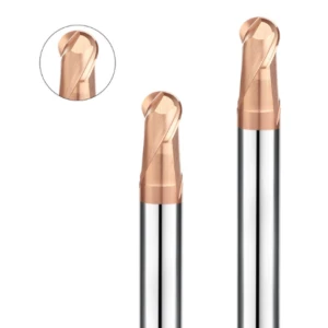
The Core of Surface Finish: Decoding HRC65 Ball Nose End Mill Geometry
Often, you dial in your speeds and feeds, yet the workpiece still shows fine chatter marks or visible steps between passes. When we troubleshoot surface finish issues on-site, over 60% of the time the culprit isn’t spindle runout—it is tool geometry unsuited for hard milling.
Effective ball nose end mill geometry for hardened steel is a micron-level balancing act between edge sharpness, chip evacuation, and core rigidity. If any angle is ground too aggressively or too conservatively, you will see it immediately in your Ra surface roughness and manual polishing hours.
Negative Rake & Reinforced Core Diameter: Eliminating Deflection and Chatter in Deep Cavities
We recently helped a German automotive bumper mold maker eliminate sidewall chatter in deep ribs. Their long-reach cutters (over 8xD) were leaving rhythmic wave marks on steep walls. We redesigned the tool by increasing the core diameter from 55% to over 68%—trading deep flute space for bending rigidity—and ground a -6° to -8° negative rake angle to dampen high-frequency vibration.
Of course, this geometry requires smart application trade-offs. Because chip space is tighter, you cannot use a heavy-core carbide ball nose end mill for slotting or heavy roughing. However, in deep-cavity semi-finishing and finishing with under 0.05mm stock, it holds deflection to a few microns and completely eliminates wall chatter.
How Ball Radius Tolerance (±0.003mm) and Flute Polishing Deliver an Ra0.2 Mirror Finish
In optical and medical mold finishing, a standard ±0.01mm ball radius tolerance simply won’t cut it. Using a Hexagon CMM, we measured parts before and after mid-program tool changes with a standard ball end mill. That tiny 0.01mm profile shift left visible witness lines across the cavity, forcing mold makers to spend hours hand-stoning the blend—which is why we hold our precision ball profiles within ±0.003mm.
Flute surface finish is the other detail shops frequently overlook. High-temperature chips from dry hard milling easily weld onto rough grinding marks inside the flutes, scratching the finished wall on the next rotation. Adding a micro-honing and mirror-polishing step to the flutes lets hot chips slide out cleanly, allowing you to hit an Ra0.2 mirror finish straight off the machine.
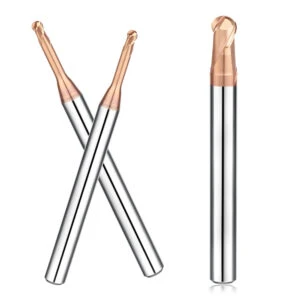
2-Flute vs 4-Flute Ball Nose End Mills: How to Choose for Finishing Hardened Steel?
When reviewing process sheets from North American and European shops, we often see a costly habit. Many operators run the same 2 flute ball nose end mill from semi-finishing straight through final finishing, or use multi-flute cutters on uneven stock. Both “one-size-fits-all” shortcuts either double your cycle time or snap the cutter inside tight corners.
In hard milling, flute count is never a simple “more is better” equation. It is a strict trade-off between chip evacuation space and core rigidity. To maximize spindle efficiency and tool life, you must switch flute counts decisively based on stock allowance, cavity depth, and target surface finish.
When Must You Use a 2 Flute Ball Nose End Mill?
Whenever your operation involves semi-finishing, clearing deep slot roots, or milling narrow gaps, stick to a 2-flute design. During an on-site audit at a French precision mold shop, operators were using a 4-flute cutter to clear 18mm-deep stiffening ribs. Chips jammed in the narrow flutes under high heat, snapping the tip off at the base.
Switching to a 2 flute ball nose end mill provides wider chip gullets that clear hot swarf instantly. While a 2-flute core has slightly lower rigidity at long overhangs, smooth chip evacuation always comes first when stock exceeds 0.1mm. Slowing your feed slightly is far cheaper than snapping a cutter inside a $30,000 hardened mold insert.
Why Switch to a 4 Flute Ball Nose End Mill for High-Finish, Large-Surface Machining?
Once semi-finishing leaves a uniform 0.02mm to 0.04mm stock allowance, running a 2-flute tool wastes valuable spindle hours. At this stage, chips are fine powder, so evacuation is no longer a bottleneck. We advise switching to a 4 flute ball nose end mill—keeping the same chip load ($F_z$) nearly doubles your table feed rate and cuts finishing cycle times by over 35%.
A 4-flute geometry also features a thicker core diameter and balanced radial cutting forces. During high-speed machining (HSM), this suppresses deflection and holds surface roughness steady at Ra 0.2–0.3. Just ensure your preceding semi-finishing pass leaves uniform stock, or localized heavy spots will pack the smaller flutes.
Challenges in Precision Connector and Optical Mold Machining: Strategies to Prevent Tool Breakage with Micro Ball Nose End Mills
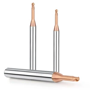
When milling 3C connectors or optical lens inserts with R0.1 to R0.5 cutters, standard selection rules break down. At this micro scale, tools are almost exclusively 2-flute and fail from sudden mechanical snapping rather than gradual wear. While troubleshooting a Minnesota medical mold shop last year, our dial indicator revealed 0.008mm runout on their shrink-fit holders—tripling the impact load on one flute of an R0.2 cutter.
To run micro ball nose end mills reliably above 60 HRC, we enforce two strict rules on the shop floor. First, total clamping runout must stay under 0.003mm using precision shrink-fit or hydraulic holders. Second, match the neck taper precisely to the cavity draft angle, stepping down multiple neck lengths rather than forcing one long-reach cutter to take heavy loads.
Shop-Floor Tested: Cutting Parameters for HRC65 Ball Nose End Mills
When supporting mold shops across the US and Europe, we frequently see two costly extremes. Some operators apply aluminum high-speed parameters to hardened steel, burning the tip red-hot on entry. Others run overly conservative speeds and feeds, causing severe work-hardening and abrasive rubbing. No single chart fits every setup—even on identical H13 steel, adding 10mm of overhang changes your safe cutting load.
The HRC65 ball nose end mill cutting parameters below are verified across our lab and customer production floors. They prioritize edge thermal stability first, then unlock spindle efficiency. Use them as a safe baseline for initial test cuts, then fine-tune based on your machine rigidity, holder runout, and cavity depth.
Reference Table for Spindle Speed (RPM), Feed Rate, and Depth of Cut (Ap/Ae) for Hardened Steels (H13, D2, and S136)
Before dialing in these numbers, clarify one concept often miscalculated on the shop floor: Effective Cutting Diameter (Deff). Taking a shallow 0.03mm finishing pass on a flat or gentle slope engages only a tiny circle near the ball tip, cutting your actual linear speed to one-third of the nominal diameter calculation. Never calculate RPM from nominal tool diameter, or you will plow the steel and chip the edge—keep your effective surface speed (Vc) between 60 and 90 m/min.
The following HRC65 ball nose end mill cutting parameters apply to 60–65 HRC steels at standard overhangs (L/D ≤ 5). When milling high-carbon, high-chromium D2 steel, start with feed rates 15% lower than listed and ramp up once the cut sounds steady:
| Ball Radius (R) | Nominal Dia. (D) | Spindle Speed (RPM) | Feed Rate (mm/min) | Axial Depth Ap (mm) | Radial Stepover Ae (mm) |
Recommended Application
|
| R0.5 | 1.0 mm | 28,000 – 36,000 | 1,200 – 2,200 | 0.015 – 0.025 | 0.02 – 0.04 |
Optical & connector micro-finishing
|
| R1.0 | 2.0 mm | 20,000 – 26,000 | 1,800 – 3,200 | 0.02 – 0.04 | 0.03 – 0.06 |
Precision corner picking & steep walls
|
| R2.0 | 4.0 mm | 13,000 – 17,000 | 2,400 – 4,000 | 0.03 – 0.05 | 0.05 – 0.10 |
Medium mold cavity semi/finishing
|
| R3.0 | 6.0 mm | 9,500 – 12,500 | 2,200 – 3,800 | 0.04 – 0.07 | 0.08 – 0.15 |
High-speed automotive surface milling
|
| R5.0 | 10.0 mm | 6,000 – 8,000 | 1,800 – 3,200 | 0.05 – 0.10 | 0.12 – 0.22 |
Large hardened mold base finishing
|
Cooling Strategies: Dry Machining vs. Cold Air vs MQL (Minimum Quantity Lubrication)
Our first rule for hard milling cooling is non-negotiable: shut off water-soluble flood coolant immediately. Above 60 HRC, cutting zone temperatures spike past 900°C (1,650°F). Flood coolant triggers severe thermal shock, creating micro-cracks across the high-aluminum nano-coating within minutes and causing complete delamination faster than running completely dry.
Based on our comparative shop-floor trials, high-pressure cold air (5–6 bar cold air gun) or MQL delivers the best stability alongside these HRC65 ball nose end mill cutting parameters. Cold air blasts hot chips away cleanly on open surfaces while letting the coating’s red hardness insulate the carbide. For deep cavities, sticky S136 stainless steel, or micro-tooling, switching to MQL cuts flute friction and extends cutting distance by roughly 25%.
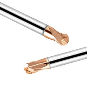
How to Consistently Extend HRC65 Ball Nose End Mill Tool Life by 40%? 4 Practical Insights from Technical Support
When comparing carbide ball nose end mills across brands, many buyers blame tool life solely on coatings or carbide grades. Yet our on-site engineers see a different reality every week. Even with identical tools from the same batch running the same program, actual lifespan can vary by over 100% between two adjacent machines.
Boosting HRC65 ball nose end mill tool life by 40% or more rarely comes from buying pricier cutters. It comes from dialing in clamping rigidity, effective cutting angles, and CAM toolpath transitions. Implement even two of the shop-floor adjustments below, and you will see immediate savings at the spindle.
Tilt-Angle Machining (15°–30° Inclination): Avoiding the Zero-Velocity Zone at the Ball-Nose Center
If you run a 5-axis machining center—or use a fixed-angle tilting holder on a 3-axis mill—tilt the spindle or part by 15° to 30°. Because cutting speed at the exact center of a ball nose is zero, vertical plunges force the tip to plow rather than shear. Tilting at least 15° shifts the cut onto the spherical side edge, where linear velocity and chip evacuation are vastly superior.
While optimizing a 5-axis finishing setup for a Swiss watchmaking shop, we changed their tilt angle from 0° to 20°. That single tweak jumped HRC65 ball nose end mill tool life from 45 minutes to over 110 minutes and erased bottom witness marks. Always run collision checks in CAM for deep pockets, but on open or medium-depth surfaces, tilting is an easy win.
Tool Clamping (Shrink-Fit vs. Hydraulic Holders) and Controlling the Overhang Ratio (L/D)
When troubleshooting sudden chipping or chatter on-site, checking the holder on a runout gauge solves 80% of cases. Old collets or operators leaving an extra 10mm of stick-out are usually to blame. In hard milling, every 0.005mm of radial runout doubles the impact load on one flute, cutting HRC65 ball nose end mill tool life in half.
Retire standard ER collets for hardened steel finishing and switch to shrink-fit or hydraulic chucks holding under 0.003mm runout. Shrink-fit holders offer slim clearance for deep cavities, while hydraulic chucks excel at dampening vibration on longer reaches. Keep your overhang ratio (L/D) tight—extending from 4xD to 6xD cuts vibration resistance by nearly 35%, so never leave a single extra millimeter exposed.
Uniformity of Finishing Allowance and Optimization of Climb Milling Paths
Finishing ball end mills rarely fail from steady heat; they snap from sudden depth spikes. Rushing straight from a wide-stepover roughing pass into finishing leaves 0.15mm or more of residual stock in corners. When a cutter programmed for a 0.03mm pass slams into those steps at high speed, radial shock causes instant micro-chipping.
Always add a rest-machining semi-finishing pass to equalize stock, and lock your CAM toolpaths strictly to climb milling. Conventional up-milling rubs from zero chip thickness, accelerating flank wear and work hardening. Finally, replace vertical plunges and sharp corners with smooth arc lead-ins and lead-outs to keep cutting loads completely steady.
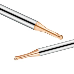
As an HRC65 Ball Nose End Mill Manufacturer, How Do We Ensure Batch-to-Batch Consistency?
Mold shop supervisors across the US and Europe often tell us their biggest headache isn’t test-cut performance. It is when a bulk reorder runs the exact same program and suddenly chatters or chips early. For lights-out automated cells, batch consistency matters far more than peak single-tool life, because one off-spec batch ruins an entire overnight shift.
As a dedicated HRC65 ball nose end mill manufacturer with 16 years in hard milling, we know your speeds, feeds, and toolpaths depend on repeatable geometry. Whether it is our 0.2–0.4μm ultra-fine carbide grade or our -6° negative rake angle, every tool must leave the grinder identical. If wheel wear isn’t compensated properly during production, shop-floor adjustments can never save the cut.
From 5-Axis Grinding Wheel Dressing to Full-Scale Optical Inspection via Zoller: Our 4-Stage Pre-Shipment QC
We grind every hardened-steel ball end mill in a single setup on Swiss Rollomatic and German Walter 5-axis CNC grinders. Great machines are only the baseline—our four-stage QC locks in repeatability. First, we run ultrasonic flaw detection and cobalt metallographic checks on incoming carbide rods; second, we execute high-frequency in-process wheel dressing so abrasive wear never alters the ball radius.
Third, every batch first-article and statistical sample goes onto a German Zoller optical inspection machine to verify ball profile accuracy within ±0.003mm, along with helix and core specs. Fourth, we test AlCrSiN/AlTiSiN coating thickness and run Rockwell indentation adhesion checks to guarantee zero delamination above 900°C.
Custom Geometry Solutions for Deep Cavities and High-Hardness Applications
Catalog standards handle 70% of hardened steel jobs, but the toughest mold work lives in the remaining 30%—like narrow ribs with minimal draft or 65 HRC tool steels. As a primary HRC65 ball nose end mill manufacturer, we engineer custom geometry modifications directly from your 3D mold drawings and hardness specs, delivering tailored step-neck or heavy-core prototypes within 48 hours.
Use the failure checks, geometry rules, and parameter baselines in this guide to audit your current shop-floor setup. If you are fighting deep-cavity chatter, corner-picking breakage, or heavy bench-polishing hours on steels above 60 HRC, send your material grade, measured hardness, overhang, and problematic toolpath to our engineering team for a free technical review.