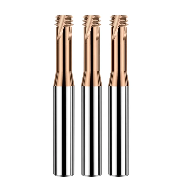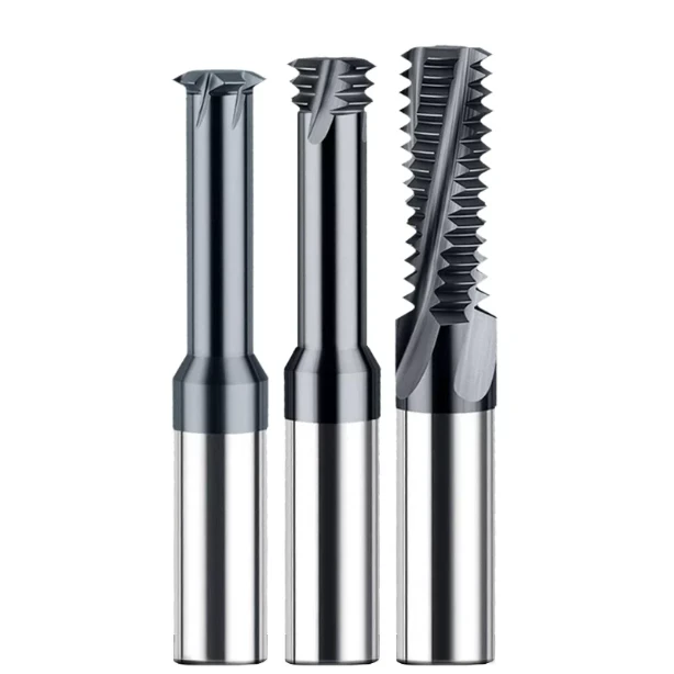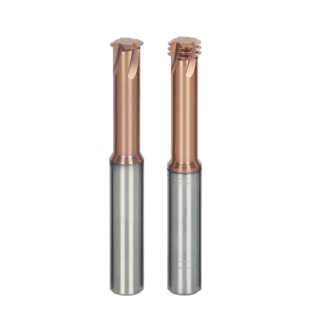


A process supervisor at a German automotive die-casting facility once sent us a photo of a scrapped H13 mold core. Hardened to HRC64 and valued at tens of thousands of euros, the core was ruined during final finishing when a standard imported multi-flute thread mill snapped inside an M8 blind hole. Subsequent EDM removal damaged the surface and delayed the entire production line.
Over sixteen years of delivering thread milling solutions across Europe and North America, we see this exact failure repeatedly. Once steel reaches HRC60–65, its tensile strength spikes and cutting shifts from shearing to high-stress extrusion. Off-the-shelf cutters fail here due to three compounding limits:
-
Chip evacuation and torque overload: Fine chips pack at the bottom of blind holes, while multi-tooth radial forces instantly exceed the carbide’s transverse rupture strength.
-
Tool deflection and gauge failure: When cutting D2, M2, or ASP23 steel, standard core diameters flex under load, pushing pitch diameters out of tolerance.
-
Thermal coating delamination: In dry or MQL hard milling, cutting zone heat tops 850°C, rapidly oxidizing standard PVD coatings and dulling the edge within ten holes.
Simply lowering spindle speeds or feed rates rarely solves these issues. The real breakthrough requires a custom HRC65 thread mill built around ultra-fine-grained carbide blanks, micron-level edge honing, and high-temperature AlCrSiN coatings. Every geometric micro-adjustment directly dictates tool life and your final cost per hole.
Is your shop fighting broken taps, inconsistent tool life, or failed thread gauges in hardened steel? Have you ever dropped your feed rate to the absolute minimum, only to watch the cutter still snap at the bottom of a blind hole?
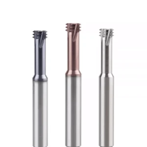
Why Do Standard Cutters Fail on Thread Mill for High Hardness Materials?
When facing hardened die steel, many engineers grab a general-purpose carbide cutter and drop speeds and feeds to “take it slow.” In our experience analyzing hundreds of failures, this conservative approach actually accelerates breakage. Above HRC60, steel loses nearly all plasticity, turning smooth shearing into violent extrusion.
When developing a thread mill for high hardness materials, we require clients to send back broken tools and chips for electron microscope analysis. Over 85% of premature failures stem from three overlapping physical bottlenecks rather than normal flank wear: chip packing, radial deflection, and thermal shock.
Sudden Chipping Due to Poor Chip Evacuation in Blind and Deep Holes
A U.S. Midwest stamping die shop contacted us while milling 2.5xD M10 blind holes in HRC63 D2 steel. Their imported multi-tooth cutters were snapping unpredictably every three holes. Inspecting their toolpaths and chips revealed shallow flutes that trapped fine, powdery debris at the bottom of the blind hole.
Without high-pressure coolant reaching the hole bottom, these hardened chips wedged into the threads and triggered secondary re-cutting. Spindle load spiked in under 0.2 seconds, snapping the carbide neck. Pulling a multi-ton mold insert for EDM extraction costs thousands of dollars—making slower, safer chip evacuation far smarter than chasing multi-tooth cycle times.
Tool Deflection and Gauge Failures in Thread Mill Technical Support
In our daily thread mill technical support, operators often report a frustrating issue: the tool survives, yet the GO gauge jams or the NO-GO gauge fails to lock. We recently inspected HRC64 stainless medical parts from a Swiss client on our CMM. The threads showed a clear “tapered” distortion—wider at the top and tighter at the bottom.
Extreme radial cutting forces in HRC62–65 steel cause standard slender shanks to flex elastically. As the tool feeds deeper, the longer overhang increases deflection. Tweaking the cutter radius offset (D-value) only masks the symptom; the moment material hardness fluctuates, your pitch diameter drifts right back out of tolerance.
Rapid Delamination of Conventional Coatings Above 800°C
Many machinists apply HRC35 quenched-and-tempered habits to hardened steel, assuming speeds under 30 m/min will protect standard TiAlN coatings. However, our infrared thermal imaging tests on HRC65 powder-metallurgy steel prove otherwise. Because hardened steel conducts heat poorly, over 80% of thermal energy concentrates in a 0.1 mm zone at the tip, exceeding 850°C.
At this temperature, aluminum in standard TiAlN oxidizes into a brittle layer that flakes off under cutting impact. Once bare carbide hits the hardened workpiece, crater wear and micro-chipping destroy the edge within seconds. For dry or MQL hard milling, general-purpose coatings cannot survive batch production—you must step up to thermally stable nanocomposite coatings.
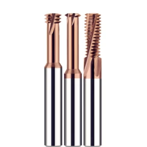
Solid Carbide Thread Mill Geometry for HRC65 Steels
When machining hardened mold steels above HRC60, tools rarely fail from a lack of sharpness. Instead, conventional cutting edges are too fragile at the microscopic level. After investigating hundreds of breakages across North America and Europe, we found that high-hardness milling requires structural reinforcement to distribute cutting stress deep into the carbide substrate.
Bei der Entwicklung solid carbide thread mill geometry, we ignore standard quenched-and-tempered parameters. Our designs balance two core trade-offs: cutting radial forces and boosting edge toughness. Every micro-adjustment—from rake angles to flute count—keeps the tip intact through tens of thousands of intermittent impacts per minute.
Negative Rake Angle Reinforcement and Micron-Level Edge Preparation
Under an electron microscope, a freshly ground carbide edge looks like a jagged saw blade. If that untreated edge hits HRC65 steel, microscopic notches act as stress risers and chip on first contact. On our five-axis CNC grinders, we shift the rake angle to a negative -3° to -6° to protect the tip under compressive load.
Next, we use wet abrasive blasting or brush honing to hold the edge radius strictly between 0.008 mm and 0.015 mm. Below 0.006 mm, hard carbides in the steel still chip the edge. Above 0.02 mm, excessive rubbing triggers severe work hardening and tool deflection.
Neck Relief and Variable Helix Design for Vibration Suppression
Deep mold cavities and tall bosses often push thread milling overhangs to 3xD or 4xD. When designing a kundenspezifische Gewindeschneidanlage for long reach, we maximize the core diameter while preserving flute space for chip evacuation. A large-radius transition between the neck and shank eliminates stress fractures under heavy side loads.
To stop high-frequency chatter in deep holes, we replace standard flutes with a 35°/38° variable helix and unequal tooth spacing. Staggering each tooth’s entry breaks up harmonic resonance before it starts. Even on machines with moderate spindle rigidity, the cut sounds noticeably deeper and steadier.
Single-Form vs Multi-Tooth Designs for Reducing Radial Forces
Many buyers assume multi-tooth cutters are always faster because they finish a thread in one pass. In HRC65 steel, engaging a dozen teeth simultaneously multiplies radial forces exponentially. That cumulative side load quickly snaps slender necks or pushes pitch diameters out of tolerance.
For HRC62–65 workpieces, we advise dropping full-profile cutters in favor of single-form or 3-tooth designs with multi-pass Z-axis step-downs. While cycle time increases by a few seconds per hole, cutting load per tooth drops by over 70%. You eliminate breakage risk and cover multiple hole diameters with one pitch—lowering overall cost per part.
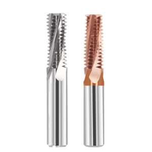
Solid Carbide HRC65 Thread Mill Substrate and Coating
Even perfect geometry fails within minutes if the carbide substrate lacks transverse rupture strength or the coating burns off. When developing a solid carbide HRC65 thread mill, we remind shop engineers that hard milling is a “hard-on-hard” battle against workpiece carbides. Predictable tool life only happens when internal substrate toughness supports an effective thermal barrier.
Before grinding any high-hardness batch, we match the carbide grade and PVD coating to your exact alloy and coolant setup. High-vanadium powder metals demand completely different metallurgy than standard hot-work die steels, making one-size-fits-all tooling a costly gamble.
Empirical Flexural Strength of Ultra-Fine-Grained Carbide Rods (0.2–0.4 μm)
Many buyers assume HRC65 steel requires the lowest-cobalt, hardest carbide rod available. Our lab tests on imported tungsten carbide blanks prove that ultra-low cobalt makes cutters dangerously brittle. Under intermittent thread milling impacts, even minor collet runout can snap low-cobalt necks clean off.
Through shop-floor validation, we standardized on 0.2–0.4 μm ultra-fine-grained carbide with a 10% to 12% cobalt binder. This “sweet spot” delivers high hot hardness while holding transverse rupture strength above 4200 MPa. Trading a fraction of theoretical wear resistance for impact toughness prevents sudden failures when hitting localized hard spots.
Performance Comparison of Thread Mill Coating in Dry Hard Milling
When dry cutting temperatures exceed 850°C, selecting the right thread mill coating dictates how many holes each cutter survives. In a test for a German automotive mold shop, we milled HRC64 blind holes using only compressed air. Tools with conventional AlTiN coatings oxidized, delaminated, and lost gauge accuracy by hole 45.
Switching to an AlCrSiN nanocomposite coating under identical feeds and speeds pushed tool life past 180 holes, with the final threads still passing NO-GO gauges. At extreme heat, silicon forms a dense amorphous oxide shield that blocks thermal transfer into the carbide. Its low friction coefficient also helps fine chips slide smoothly out of the flutes.
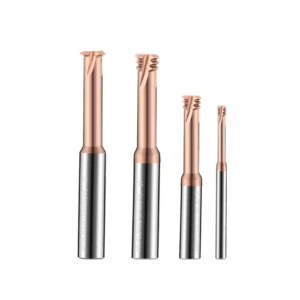
Practical Case Studies: UN Thread Milling Cutter & Micro Thread Milling Cutter
While metric coarse cutters sit on every distributor’s shelf, our engineering team spends most of its time solving off-catalog jobs. Across North American and European aerospace, medical, and oil-and-gas shops, combining HRC60+ steel with special UN profiles or micro bores drops your margin for error to zero.
A few microns of root radius error or 0.005 mm of spindle runout can scrap an entire batch of high-value parts. Whether we are building a heavy-duty UN thread milling cutter or an orthopedic micro tool, we tie tolerance compensation directly to your machine’s dynamic rigidity during the initial design stage.
Customizing Root Radii and Tolerance Zones for Non-Standard UN Profiles
North American aerospace and downhole oil-and-gas shops frequently ask us to cut Class 3B UNJ or UNEF internal threads in HRC62 stainless or nickel alloys. Standard 60° sharp-vee cutters fail specialized UNJ root gauges and leave sharp corners that trigger fatigue cracks under cyclic loads.
To solve this, we inspect your GO/NO-GO gauges on an optical projector and dress our five-axis grinding wheels with a micron-accurate diamond roller. Building a 0.004–0.006 mm elastic deflection allowance right into the wheel lets you hit Class 3B gauge tolerances in one pass without manual rework.
Preventing Tool Breakage in a Micro Thread Milling Cutter (Below M1.6)
Swiss and U.S. medical and connector mold shops routinely thread M1.0, M1.2, and M0.8 blind holes in HRC64 steel. When running a micro thread milling cutter under 1 mm in diameter, collet runout above 0.003 mm forces one flute to carry over 80% of the load, snapping the neck like glass on entry.
We hold our own grinding runout under 0.002 mm and specify strict CAM toolpaths: climb milling only, G02/G03 circular entry and exit, and 3 to 4 radial step-downs. Adding a few seconds of cycle time is a smart shop-floor trade-off compared to digging a snapped micro tool out of a blind hole.
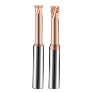
From Blueprint Evaluation to Trial-Cut Validation: Thread Mill Technical Support & Solutions
Looking across blind-hole chip packing, overhang deflection, and 850°C thermal barriers, one rule stands out: no cutter works in isolation from your machine’s rigidity. When delivering thread milling solutions, we never hand you a standard catalog and leave you to guess.
Reliable hard-milling performance requires aligning our geometry with your exact shop-floor constraints from day one. From blueprint tolerance breakdowns to on-machine prototype validation, every adjustment relies on a closed loop of real cutting data.
5 Key Parameters Our Engineering Team Checks Upon Receipt of Blueprints
Before quoting any custom job, our thread mill technical support team verifies five parameters that dictate tool geometry and survival:
-
Material grade & actual hardness: HRC63 ASP23 powder metal wears edges far faster than HRC63 H13 steel, dictating tooth count and edge honing.
-
Thread vs. pilot hole depth: We calculate chamfer clearance within 1–2 pitches so chips never pack at the bottom of blind holes.
-
Spindle RPM & torque curve: Checking low-end torque versus 20,000+ RPM micro-tool needs sets your ideal helical interpolation feed.
-
Coolant & holder setup: Through-spindle pressure (Bar), MQL, or air blast—paired with shrink-fit, hydraulic, or ER holders—determines coating thickness and runout limits.
Small-Batch Thread Mill Sample Order and Closed-Loop On-Site Feedback
Even after thorough calculations, we recommend running a small-batch thread mill sample order before full production. Within 7 to 10 business days of parameter sign-off, we ship your ground and coated sample alongside a custom parameter card listing exact RPM, feed per tooth (Fz), and Z-axis step-downs.
Once you run the sample, share your spindle load readings, chip color, and GO/NO-GO gauge feel at the top and bottom of the hole. If you are fighting broken cutters or tight gauges in hardened steel, UNJ profiles, or sub-M1.6 blind holes, review those five parameters above—and send us your drawings, measured hardness, or failed tool photos so we can dial in your process together.