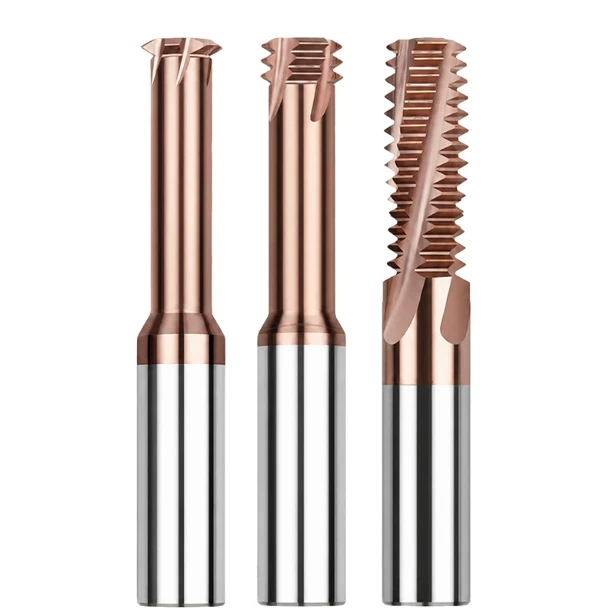


A Texas mold shop scrapped an H13 mold insert heat-treated to 63 HRC. During the final finishing pass, they tried tapping an M8 blind hole with a “high-hardness” carbide tap, and it snapped flush at the bottom. Removing the broken tap via EDM delayed delivery and caused micro-cracks in the surrounding hardened layer.
Over our 16 years in tool R&D and technical support across North America and Europe, we have seen this exact failure repeatedly. Once a workpiece reaches 58–65 HRC, traditional tapping fails because excessive radial torque and tight chip flutes cause the tool to seize.
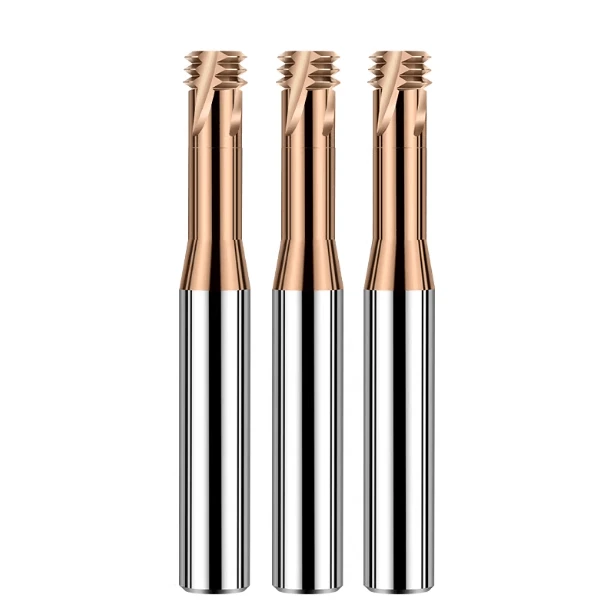
To eliminate this risk, precision mold shops and aerospace manufacturers are switching to carbide thread milling cutters for heat-treated steel. Using helical interpolation, these tools rely on interrupted cutting to keep radial forces low. Still, many shops struggle with tool selection and purchasing:
-
Why do some cutters rated for 65 HRC chip after 20 holes, while others exceed 100 holes?
-
For deep blind holes, should you choose a rigid multi-tooth design or a single-tooth cutter for better chip evacuation?
-
Beyond unit price, what geometry and coating specs should buyers verify when comparing HRC65 thread milling cutter price quotes?
To help process engineers and buyers make confident decisions, we compiled our real-world honing data, coating test results, and shop-floor feed strategies into this guide.
When threading parts over 60 HRC, have you ever lost a nearly finished workpiece to a broken tap—or struggled with chatter and undersized threads after switching to thread milling?
Why We Always Advise Clients to Replace Taps with a Carbide Thread Milling Cutter
Whenever a customer’s workpiece exceeds 58 HRC, our first recommendation is simple: pull the tap out of the magazine. This isn’t a knock on tap quality; it comes down to cutting physics. A tap engages the full thread profile simultaneously, whereas a carbide thread milling cutter uses three-axis helical interpolation for light, intermittent contact.
Shop managers often hesitate at the higher upfront tool cost and slightly longer cycle times. However, in hardened steel, overall yield rate and downtime drive your true cost per part—not an extra ten seconds of spindle time. Once you experience a broken tap in a blind hole, prioritizing process control becomes an obvious choice.
The True Cost of a Broken Tap in 58–65 HRC Workpieces: From EDM Removal to Total Scrap
While supporting a stamping die maker in Baden-Württemberg, Germany, we saw this exact scenario play out. They were tapping M6 blind holes in 62 HRC DIN 1.2379 (D2) tool steel; the first 14 holes went fine, but the tap snapped flush on hole 15. Because it was a blind hole, they had to pull a 90%-finished die insert worth thousands of euros and ship it out for EDM removal.
A high-hardness tap costs roughly $40, yet external EDM labor and logistics topped $350. Worse, the EDM process left a heat-affected zone that weakened thread engagement, nearly scrapping the entire block. Tapping above 58 HRC is pure gambling, whereas a worn thread mill simply retracts cleanly without damaging your part.
Cutting Logic for a Carbide Thread Cutter for Heat Treated Steel: How Interrupted Cutting Reduces Radial Forces
Standard taps seize in ultra-hard steel because their massive contact area traps chips inside confined flutes. Even minor chip compression spikes radial torque past the carbide’s breaking point. A well-engineered carbide thread cutter for heat treated steel contacts the hole wall with only a tiny arc, producing short, comma-shaped chips that clear effortlessly with air or coolant.
Still, we never recommend cutting full thread depth in a single pass at 63–65 HRC. We instruct engineers to split the radial depth into two or three passes—typically 65% on the first pass, 25% on the second, and 10% for a spring finishing pass. You trade a few seconds of cycle time to cut radial spindle load in half and prevent tip micro-chipping.
The Key to Tool Life in High-Hardness Machining: A Practical Breakdown of Thread Milling Cutter Geometry
When sourcing tools for hardened steel, most buyers and engineers look first at coating color or nominal hardness ratings. Yet after grinding hundreds of standard and custom cutters daily on our 5-axis machines, we know thread milling cutter geometry is what truly survives 65 HRC impact. Hardened steel generates extreme cutting resistance, instantly amplifying any micron-level edge flaw into chipping or chatter.
During a failure analysis for a Swiss medical mold maker, we found their imported cutters produced distorted threads after just 20 holes—not from soft carbide, but from unoptimized flute geometry and edge prep. True tool life comes from matching the substrate’s microstructure with exact cutting angles rather than chasing surface-level specs.
Substrate and Coating Combinations: Our Empirical Comparison of Ultra-Fine-Grain Tungsten Carbide and AlTiSiN Coatings for Materials Above 62 HRC
In 62–65 HRC mold steels like SKD11 or H13, standard TiAlN coatings rarely last beyond 15 to 20 standard M8 holes before heat triggers delamination and edge micro-chipping. Our bench tests confirmed that an ultra-fine-grain tungsten carbide substrate—under 0.4 microns with 8% to 10% cobalt—delivers the best balance of hot hardness and flexural strength.
Instead of thick, brittle coatings, we apply a 2.5-micron nanocomposite AlTiSiN layer that consistently pushes tool life past 85 holes at 64 HRC under dry or oil-mist cooling. Wear develops as a smooth crescent crater rather than sudden breakage, though ultra-fine-grain blanks require spindle taper runout under 0.005 mm (0.0002″) to perform reliably.
Designing Rake Angles, Relief Angles, and Core Diameter: Preventing Tool Deflection and Chatter in High-Hardness Machining
Budget cutters often use positive rake angles for a “light” cut, which works on pre-hardened steel but shatters like glass within three revolutions at 65 HRC. We grind a zero or negative rake angle (-3° to -5°) and apply controlled edge honing to create a micro-radius, converting destructive shear stress into compressive force.
We also maximize the core diameter and reduce the primary relief angle to stiffen the cutting teeth against radial deflection. While a larger core slightly reduces flute volume, hardened steel produces tiny broken chips that evacuate easily, ensuring every deep hole passes Go/No-Go gauge inspection on the first try.
Selecting Tool Structure and Thread Profile: Matching the Right Tool to Your Specific Application
Supporting US and European CNC shops has taught us that even at an identical 63 HRC, blind-hole depth, batch size, and assembly tolerances dictate completely different tool designs. Relying on one “universal” cutter leads to snapped tools in deep blind holes or sluggish cycle times on high-volume production lines.
To machine internal threads reliably in hardened steel, you must evaluate tooth count and thread profile separately. We always lock in the thread depth-to-diameter ratio and tolerance class first, then balance tool rigidity, chip clearance, and per-part cycle time.
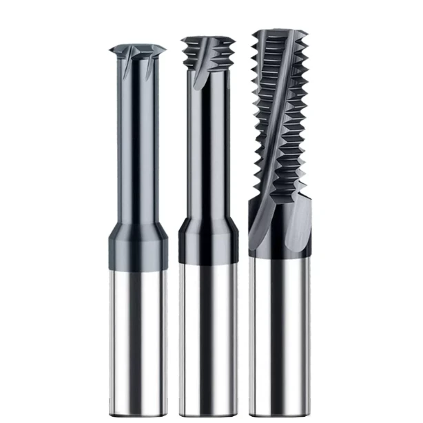
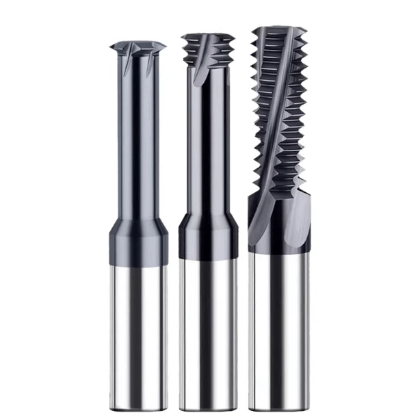
Balancing Rigidity and Chip Evacuation: HRC65 3 Tooth Thread Milling Cutter vs. Single Point Thread Milling Cutter
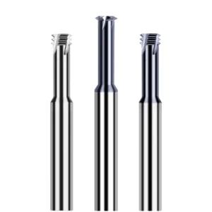
For standard holes up to 2xD in production batches, we recommend an HRC65 3 tooth thread milling cutter. Three evenly spaced flutes balance radial forces and provide far greater rigidity than slender single-flute tools, completing threads in just a few Z-axis helical passes on automated lines.
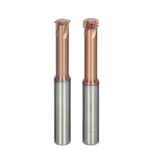
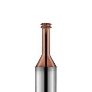
Once hole depth exceeds 3xD—or when threading micro blind holes under M4—you must switch to a single point thread milling cutter. Its single cutting tip and heavily relieved neck open wide chip-evacuation channels and minimize radial deflection, trading a few extra helical passes for complete deep-hole safety.
Practical Experience: Using a Full Profile Thread Milling Cutter to Eliminate Secondary Deburring in High-Hardness Steel Components
At a precision hydraulic valve manufacturer in the US Midwest, operators were milling dozens of port threads into 61 HRC alloy steel blocks using partial-profile cutters. Although pitch diameters passed inspection, technicians spent hours manually scraping crest burrs under magnifiers, risking costly scratches on critical sealing faces.
We switched their line to a custom-pitch full profile thread milling cutter, which finishes the thread flanks and forms smooth, flat crests simultaneously. Manual deburring disappeared overnight and Go/No-Go pass rates exceeded 99%, though you should weigh this gain against higher inventory costs since full-profile tools are strictly pitch-specific.
Common Pitches and Pilot Hole Tolerances for a Metric Thread Milling Cutter
Never use standard carbon-steel drill charts when setting up a metric thread milling cutter above 60 HRC. Hardened steel springs back slightly after cutting, and micron-level tool deflection can leave finished threads too tight for a Go gauge.
| Nominal Size & Pitch | Standard Pilot Hole (mm) | 60–65 HRC Recommended Pilot Hole (mm) |
Initial Wear Offset
|
| M4 × 0.7 | 3.3 | 3.35 – 3.38 | -0.02 mm |
| M6 × 1.0 | 5 | 5.05 – 5.10 | -0.03 mm |
| M8 × 1.25 | 6.75 | 6.80 – 6.85 | -0.03 mm |
| M10 × 1.5 | 8.5 | 8.55 – 8.60 | -0.04 mm |
| M12 × 1.75 | 10.25 | 10.30 – 10.38 | -0.05 mm |
| M16 × 2.0 | 14 | 14.08 – 14.15 | -0.05 mm |
uring shop-floor trials, we ream pilot holes to the upper tolerance limit—such as 6.82 mm for M8×1.25—to cut crest friction without sacrificing 6H thread strength. We also program a negative radius wear offset (-0.02 to -0.05 mm) before the first test cut, dialing the pitch diameter straight into the center of the tolerance band after gauging.
Practical Parameters to Avoid Common Pitfalls: Tips for Preventing Tool Breakage, Based on Our On-Site Experience
Buyers often purchase a premium HRC65 thread milling cutter only to chip the tip within ten minutes and blame tool quality. When we inspect their CAM files, the culprit is almost always a single-pass full-depth cut or a top-down conventional helical path. Above 60 HRC, even the toughest carbide cutter cannot survive the sudden shock of an improper toolpath.
During on-site first-article runs at U.S. and European shops, we never push spindle speeds or feed rates first. Instead, we lock in the cutting direction and radial step-overs, allowing even operators new to hardened steel to finish entire production batches accurately.
Climb Milling and the “Bottom-Up” Toolpath: Why This Is a Golden Rule for Machining Hardened Steel
Top-down conventional milling works fine in mild steel, but it destroys cutters in hardened workpieces. Under a high-speed microscope, conventional milling rubs into the hardened surface at near-zero chip thickness, stripping the AlTiSiN coating within seconds—whereas bottom-up climb milling enters at maximum chip thickness, carrying heat away and cutting edge wear in half.
Bottom-up milling also protects your tool from chip recutting. Gravity, centrifugal force, and air blast push broken chips downward into the cleared hole bottom, whereas top-down paths drop hardened chips directly into the cutter’s path where a single 0.1 mm fragment can shatter the edge.
Radial Depth of Cut Allocation (Multi-pass): Recommended Ratio for Roughing vs. Finishing Passes (e.g., 65% / 35%)
Never attempt a full-depth single pass above 60 HRC like you would in aluminum or pre-hardened steel. While dialing in an M10×1.5 thread at a U.S. aerospace supplier, an operator tried a full-depth pass with a carbide thread milling cutter and snapped the neck before half a revolution—a problem we solved by splitting the cut into 65% roughing and 35% finishing passes.
| Werkstückhärte | Empfohlene Pässe | Radial Depth Split | Surface Speed (Vc) |
Futter pro Zahn (fz)
|
| 58 – 60 HRC | 2 Pässe | 70% / 30% | 45 - 55 m / min |
0.020 - 0.030 mm
|
| 61 – 63 HRC | 2 – 3 Passes | 65% / 35% or 50%/35%/15% | 35 - 45 m / min |
0.015 - 0.025 mm
|
| 64 – 65 HRC | 3 Pässe | 50% / 35% / 15% | 25 - 35 m / min |
0.010 - 0.018 mm
|
Near 65 HRC, we split the cut into three passes (50% / 35% / 15%) using smooth arc-in and arc-out entries to eliminate corner shock. Adding 8 to 15 seconds per hole cuts radial deflection dramatically, prevents breakage, and leaves a mirror-smooth flank finish.
B2B Procurement and Supply Chain Decision-Making: How to Evaluate and Buy HRC65 Thread Milling Cutters
Once you dial in geometry, tooth count, and multi-pass parameters, success comes down to smart sourcing. Too many Western purchasing teams send blueprints out for quotes and simply pick the lowest unit price, ending up with cheap “HRC65” cutters that chip immediately and leave engineering taking the blame.
When you prepare to buy HRC65 thread milling cutters for production, shift your focus from unit price to total cost per threaded hole. Writing strict technical acceptance standards into your purchase orders filters out trading middlemen and ensures bulk shipments match sample performance.
Deconstructing HRC65 Thread Milling Cutter Price Differences: Where Do the Real Gaps Lie Between Low-Cost Domestic Tools and Imported or High-End Custom Tools?
Buyers often ask why one M8 cutter rated for 65 HRC costs $15 while a custom or imported tool runs $45. From a 5-axis grinding plant’s cost ledger, that threefold gap in HRC65 thread milling cutter price comes down to three hidden manufacturing steps:
-
Carbide Substrate Grade: Virgin 0.4-micron ultra-fine-grain carbide blanks from Switzerland or Germany cost over twice as much as recycled blanks, delivering critical flexural strength at 63+ HRC.
-
Grinding Wheel Dressing Frequency: Precision shops dress diamond wheels every 15–20 cutters to hold tight thread profiles, whereas budget factories grind hundreds of tools per dressing and let crest radii drift.
-
Controlled Edge Preparation: Dedicated honing equipment applies a uniform 5–8 micron radius after grinding to prevent instant edge chipping—a step cheap generic tools skip entirely.
5 Rigorous Criteria for Vetting China Thread Milling Cutter Manufacturers
Many North American and European shops now source directly from Asia, where true factories sit alongside trading companies and small job shops. Before qualifying China thread milling cutter manufacturers, skip the glossy catalogs and demand five concrete proofs from their engineering team:
-
Rückverfolgbarkeit der Rohstoffe: Require specific carbide grade specs, cobalt percentage, and grain size rather than vague claims of “imported tungsten carbide.”
-
100% Optical Runout Reports: Verify every cutter is checked on a Zoller or Walter presetter with radial runout held under 0.005 mm (0.0002″).
-
100x Profile Comparator Data: For full-profile cutters, ask for optical overlay charts proving the ground thread form matches nominal standards.
-
Application & CAM Support: Confirm they run an in-house test center capable of supplying material-specific step-over ratios and initial wear offsets.
-
Custom Lead Times: Ensure they can engineer, 5-axis grind, and nano-coat extended-neck or non-standard pitch tools within 7–12 business days.
4-Point Checklist for Your Technical Team Before Placing an Order
To prevent neck interference, short reach, or wrong pitch profiles after ordering, run through this 4-point checklist before requesting quotes or drawings:
-
Actual Post-Heat-Treat Hardness: Specify whether parts sit at 58–60 HRC or 63–65 HRC to lock in rake geometry and coating thickness.
-
Hole Type & Effective Depth: Note blind vs. through holes, total drilled depth, full thread length, and any step obstructions to choose between 3-tooth and single-point designs.
-
Spindle Taper & Coolant Setup: List your spindle interface (HSK-A63, BT40), holder type (shrink-fit or hydraulic), and whether you run through-spindle coolant or oil mist.
-
Exact Alloy Grade: Specify H13, D2, SKD11, S136, or PM steel, as alloy chemistry dictates flute polish and coating selection.
If you are fighting broken taps, micro-chipping, or tight Go/No-Go gauges above 60 HRC, use this checklist to audit your current setup. Share your part prints, alloy grade, and hole depths with our engineering team, and we will gladly pull from our shop-floor test data to recommend the right tool geometry and pass strategy.