As an important tool in milling, the material, type and processing parameters of the end mill have a crucial impact on the processing effect. A deep understanding of this information can help processing personnel better select and use the end mill, thereby improving processing efficiency and accuracy and obtaining high-quality processing results.
Types and Grades of End Mill Materials
Basic Requirements for End Mill Cutting Materials
High hardness and wear resistance: At room temperature, the cutting part of the material must have sufficient hardness to cut into the workpiece; with high wear resistance, the tool will not wear and extend its service life.
Good heat resistance: The tool will generate a lot of heat during the cutting process, especially when the cutting speed is high, the temperature will be very high. Therefore, the tool material should have good heat resistance, which can maintain a high hardness at high temperatures and continue to cut. This property of high temperature hardness is also called hot hardness or red hardness.
High strength and good toughness: During the cutting process, the tool must withstand a lot of impact, so the tool material must have a high strength, otherwise it is easy to break and damage. Since the milling cutter will be subject to impact and vibration, the milling cutter material should also have good toughness to prevent it from chipping and breaking.
Common Materials for End Mills
High-speed tool steel (also called high-speed steel) is divided into general-purpose and special-purpose high-speed steel. It has the following characteristics:
- The content of alloy elements tungsten, chromium, molybdenum and vanadium is high, and the quenching hardness can reach HRC62-70. At a high temperature of 6000C, it can still maintain a high hardness.
- It has good edge strength and toughness, strong vibration resistance, and can be used to manufacture tools with normal cutting speeds. For machine tools with poor rigidity, high-speed steel milling cutters can still cut smoothly.
- It has good process performance, and forging, processing and grinding are relatively easy. It can also manufacture tools with more complex shapes.
- Compared with cemented carbide materials, it still has disadvantages such as lower hardness, poor red hardness and wear resistance.
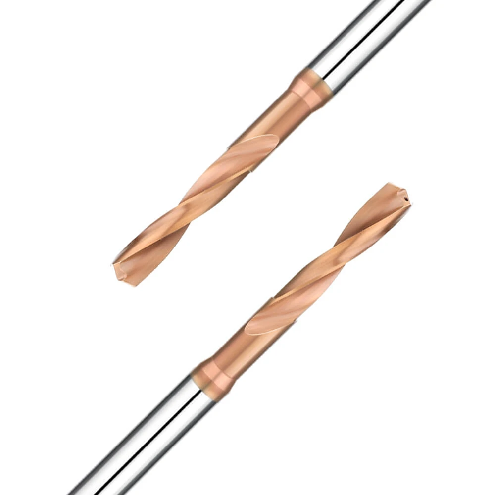
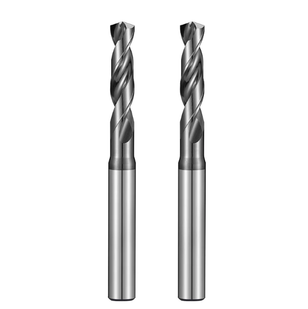
Cemented carbide: It is made of metal carbide, tungsten carbide, titanium carbide and cobalt-based metal binder through powder metallurgy process. Its main features are as follows:
It can withstand high temperatures and maintain good cutting performance at around 800-10000C. When cutting, you can use a cutting speed 4-8 times higher than that of high-speed steel. It has high hardness at room temperature and good wear resistance. It has low bending strength, poor impact toughness, and the blade is not easy to sharpen.
Commonly Used Cemented Carbide Classification
Tungsten-cobalt Cemented Carbide (YG)
Common grades are YG3, YG6, and YG8, where the numbers represent the percentage of cobalt content. The more cobalt content, the better the toughness, the more resistant to impact and vibration, but the hardness and wear resistance will be reduced. Therefore, this alloy is suitable for cutting cast iron and non-ferrous metals, and can also be used to cut roughcasts with high impact and quenched steel and stainless steel parts.
Titanium-cobalt Cemented Carbide (YT)
The grades used are YT5, YT15, and YT30, and the numbers represent the percentage of titanium carbide. After the cemented carbide contains titanium carbide, it can increase the bonding temperature of steel, reduce the friction coefficient, and slightly improve the hardness and wear resistance, but reduce the bending strength and toughness, making the properties brittle. Therefore, this type of alloy is suitable for cutting steel parts.
General Carbide
Adding an appropriate amount of rare metal carbides, such as tantalum carbide and niobium carbide, to the above two types of cemented carbides can refine their grains, improve their room temperature hardness and high temperature hardness, wear resistance, bonding temperature and oxidation resistance, and increase the toughness of the alloy. Therefore, this type of cemented carbide tool has good comprehensive cutting performance and versatility. Its grades are: YW1, YW2 and YA6. Due to its high price, it is mainly used for difficult-to-process materials, such as high-strength steel, heat-resistant steel, stainless steel, etc.
Types and Markings of End Mills
Types of End Mills
According to the Material of the End Mill Cutting Part
- High-speed steel end mills: These are used for more complex tools
- Carbide end mills: Most are welded or mechanically clamped to the cutter body
According to the Purpose of End Mill
- End mills for machining flat surfaces: cylindrical milling cutters, end mills, etc.
- Milling cutters for machining grooves (or steps): end mills, disc milling cutters, saw blade milling cutters, etc.
- Milling cutters for special-shaped surfaces: forming milling cutters, etc.
According to the Structure of End Mill
- Pointed tooth milling cutter: The truncation of the tooth back is a straight line or a broken line, which is easy to manufacture and sharpen, and the cutting edge is sharper.
- Shovel tooth milling cutter: The truncation of the tooth back is an Archimedean spiral. After this type of milling cutter is sharpened, as long as the front angle remains unchanged, the tooth shape remains unchanged, and it is suitable for forming milling cutters.
End Mill Markings
Size specification marking, cylindrical milling cutter, three-sided cutting edge, saw blade milling cutter, etc. are marked with outer diameter x width x inner hole (x angle or arc radius), end milling cutter and keyway milling cutter are generally marked with only the outer diameter.
The Main Geometric Parameters and Functions of End Mills
The Names of the Parts of the End Mill
- Base plane: a plane passing through any point on the cutting tool and perpendicular to the cutting speed at that point
- Cutting plane: a plane passing through the cutting edge and perpendicular to the base plane
- Rake face: the plane where the chips flow out
- Back face: the face opposite to the machined surface
The Main Geometric Angles and Ffunctions of Cylindrical End Mills
- Rake angle γ0: The angle between the rake face and the base surface. Its function is to make the blade sharp, reduce metal deformation during cutting, and make chips easy to discharge, so as to save cutting effort;
- Rear angle α0: The angle between the rear face and the cutting plane. Its main function is to reduce the friction between the rear face and the cutting plane and reduce the surface roughness of the workpiece;
- Spin angle 0: The angle between the tangent on the helical tooth blade and the axis of the milling cutter. Its function is to make the teeth gradually cut into and out of the workpiece, improving the cutting stability. At the same time, for cylindrical milling cutters, it also has the function of making chips flow out smoothly from the end face.
The Main Geometric Angles and Functions of End Mills
End mills have an additional secondary cutting edge, so in addition to the front angle and back angle, there are also:
- Main rake angle Kr: The angle between the main cutting edge and the machined surface. Its change affects the length of the main cutting edge involved in cutting, and changes the width and thickness of the chips
- Secondary rake angle Krˊ: The angle between the secondary cutting edge and the machined surface. The function is to reduce the friction between the secondary cutting edge and the machined surface, and affect the finishing effect of the secondary cutting edge on the machined surface
- Blade inclination angle λs: The angle between the main cutting edge and the base surface. It mainly plays the role of bevel cutting

Forming End Mills
Forming end mills are special milling cutters used for machining formed surfaces. The profile of its blade needs to be designed and calculated according to the profile of the workpiece being machined. It can be used to machine surfaces with complex shapes on general-purpose milling machines. It can ensure that the shapes are basically consistent and has high efficiency. It is widely used in batch production and mass production.
The Basic Concept of Shovel Teeth
The milling and regrinding of sharp-toothed forming milling cutters require special templates, which are difficult to manufacture and sharpen.
The tooth back of the shovel-toothed profile milling cutter is shoveled and ground on a shovel-toothed lathe. When re-grinding, only the front face is ground. Because the front face is a plane, it is more convenient to grind. At present, the profile milling cutter mainly adopts the shovel-toothed tooth back structure. The shovel-toothed tooth back should meet two conditions: the cutting edge shape remains unchanged after re-grinding; the required back angle is obtained.
Tooth Back Curve and Equation
The intersection of an end section perpendicular to the axis of the milling cutter through any point on the cutting edge of the milling cutter and the tooth back surface is called the tooth back curve of the milling cutter.
The tooth back curve should mainly meet two conditions: one is that the back angle of the milling cutter remains basically unchanged after each re-grinding; the other is that it is easy to manufacture.
The only curve that can meet the requirement of constant back angle is the logarithmic spiral, but it is difficult to manufacture. The Archimedean spiral can meet the requirement of basically constant back angle, simple to manufacture and easy to achieve. Therefore, the Archimedean spiral is widely used as the tooth back curve of the forming milling cutter in production.
According to geometric knowledge, the vector radius ρ value of each point on the Archimedean spiral increases or decreases proportionally with the increase or decrease of the angle θ value of the vector radius.
Therefore, as long as the uniform rotational motion and the uniform linear motion along the radial direction are combined, the Archimedean spiral can be obtained.
Expressed in polar coordinates: when θ=00, ρ=R, (R is the radius of the milling cutter), when θ>00, ρ<r,< p=””></r,<>
The general equation for the back of the milling cutter tooth is: ρ=R-CQ
Assuming that the scraper does not retract, the scraper tooth amount is K for each tooth angle ε=2π/z of the milling cutter. Correspondingly, the cam rise should also be K. In order to make the scraper move at a constant speed, the curve on the cam should be an Archimedean spiral, so it is easy to manufacture. In addition, the cam size is only determined by the scraper amount K value, and has nothing to do with the milling cutter diameter, number of teeth and back angle. As long as the production and sales volume are equal, the cam can be universal. This is also the reason why the Archimedean spiral is widely used on the back of the tooth of the scraper forming milling cutter.
When the milling cutter radius R and the amount of cutting K are known, C can be obtained:
When θ=2π/z, ρ=R-K
Then R-K=R-2πC /z ∴ C= Kz/2π

What Will Happen After the End Mill is Passivated
- From the shape of the chips, the chips become coarse and flaky. Due to the increase in chip temperature, the chips are purple and smokey.
- The roughness of the workpiece surface is very poor, and bright spots, gnawing marks or ripples appear on the workpiece surface.
- The milling process produces very serious vibrations and abnormal noises.
- From the shape of the blade, there are bright white spots on the blade.
- When using carbide milling cutters to mill steel parts, a lot of fire mist often flies out.
- When milling steel parts with high-speed steel milling cutters, if oil lubrication and cooling are used, a lot of smoke will be generated.
When the milling cutter is passivated, you should stop the machine in time to check the wear of the milling cutter. If the wear is light, you can use an oilstone to sharpen the cutting edge before using it again. If the wear is heavy, you must sharpen the edge to prevent excessive wear of the milling cutter.
白底-主图2.webp)