New developments in milling technology make it possible for manufacturers to save a lot of time and money by improving machining efficiency. From selecting the right milling tool for the task, to using rolling cuts in face milling, and using milling cutters for hole machining when conditions are right. Manufacturers can significantly increase production capacity without investing in new equipment.
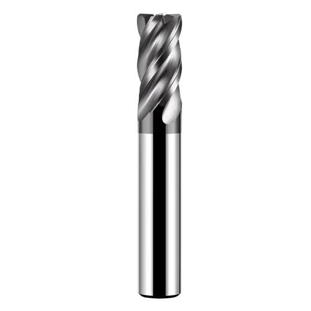
How to Choose an End Mill
When choosing the right milling cutter for the job, you must consider everything from the geometry and size of the part being machined to the material of the workpiece.
It is common in machine shops to use a 90° square shoulder milling cutter for face milling. In some cases, this choice makes sense. If the workpiece to be milled is irregular in shape or the surface of the casting causes the depth of cut to vary, a square shoulder milling cutter may be the best choice. But in other cases, you may benefit more from using a standard 45° face milling cutter.
When the cutter’s lead angle is less than 90°, the cutter’s lead angle will have a great impact on the feed per tooth it can be used for, because the chip becomes thinner and the axial chip thickness becomes less than the cutter’s feed rate. In face milling operations, a face milling cutter with a 45° lead angle will produce thinner chips. As the lead angle decreases, the chip thickness becomes less than the feed per tooth, which in turn can increase the feed rate by 1.4 times. In this case, if a face milling cutter with a 90° cut-in angle is used, productivity will be reduced by 40% due to the lack of axial chip thinning effect produced by a 45° face milling cutter.
Another important aspect of milling cutter selection that users often overlook is the size of the cutter. Many machining shops use smaller diameter cutters when face milling large parts such as engine blocks or aircraft structures, which leaves a lot of room for improving productivity. Ideally, the milling cutter should have 70% of the cutting edge involved in the cutting. For example, when milling multiple surfaces of a large part, a 50mm diameter face milling cutter will only have 35mm involved in the cutting, thus reducing productivity. If a larger diameter milling cutter is used, a lot of machining time can be saved.
How to Optimize End Mill Milling Strategies
Another way to improve milling operations is to optimize the milling strategy of the face milling cutter. When programming a face milling operation, the user must first consider the way the tool cuts into the workpiece. Often, the milling cutter simply cuts straight into the workpiece. This cut is often accompanied by a loud impact noise because the chips produced by the milling cutter are thickest when the blade exits the cut. The strong impact of the blade on the workpiece material often causes vibration and produces tensile stresses that shorten the tool life.
A better way to feed is to use the rolling cut method, that is, the milling cutter rolls into the workpiece without reducing the feed rate and cutting speed. This means that the milling cutter must rotate clockwise to ensure that it is processed in a down-milling manner. The chips formed in this way are from thick to thin, which can reduce vibration and tensile stress acting on the tool, and transfer more cutting heat into the chips. By changing the way the milling cutter cuts into the workpiece each time, the tool life can be extended by 1-2 times. In order to achieve this feed method, the programming radius of the tool path should be 1/2 of the milling cutter diameter, and the offset distance from the tool to the workpiece should be increased.
Although rolling cuts are primarily used to improve the way the tool enters the workpiece, the same machining principles can be applied to other stages of milling. For large-area flat milling operations, the common programming method is to have the tool mill along the entire length of the workpiece in succession and complete the next cut in the opposite direction. To maintain a constant radial cut amount and eliminate vibration, a combination of spiral cuts and rolling the workpiece corner is usually more effective.
Machinists are familiar with cutting noise caused by vibration, which usually occurs when the tool cuts into the workpiece or when the tool makes a sharp 90° turn while in the cutting state. Rolling the workpiece corner can eliminate this noise and extend tool life. Generally speaking, the workpiece corner radius should be 75%-100% of the milling cutter diameter, which can shorten the milling cutter’s cutting arc length and reduce vibration, and allow for higher feed rates.
To extend tool life, in face milling operations, the tool should be avoided from passing through holes or interruptions in the workpiece (if possible). When a face mill passes through the middle of a hole in a workpiece, the tool mills down on one side of the hole and up on the other side, which can cause a lot of impact on the insert. This can be avoided by programming the tool path around holes and pockets.
More and more manufacturers are using milling cutters to process holes in a spiral or circular interpolation manner. Although this method is slightly slower than drilling, it is more advantageous for many operations.

When drilling holes in irregular surfaces, it may be difficult for the drill to penetrate the workpiece along the centerline, causing the drill to deviate from the surface of the workpiece. In addition, the drill requires about 10 horsepower for every 25mm of hole diameter, which means that the optimal power value may not be achieved when drilling on a low-power machine tool. In addition, some parts require many holes of different sizes to be processed. If the machine tool has limited tool magazine capacity, using milling can avoid frequent machine tool downtime for tool changes.
When milling holes with a milling cutter, tool size becomes particularly important. If the diameter of the milling cutter is too small relative to the hole diameter, a core may form in the center of the hole during machining. When this core falls, it may damage the workpiece or the tool. If the milling cutter diameter is too large, it will damage the tool itself and the workpiece because the milling cutter is not cutting in the center and may collide at the bottom of the tool.
In addition, when milling holes with a milling cutter, the operation should be programmed from the center line of the tool. Because when helical interpolation milling with an indexable insert milling cutter is much higher at the outer edge of the insert than at the center, programmers sometimes ignore this and inadvertently use too high a feed rate that exceeds the effective operating range of the tool.
y selecting the right milling cutter to cut into the workpiece material in a way that minimizes vibration and tensile stress, and knowing when milling is more effective than drilling, manufacturers can efficiently and cost-effectively turn workpiece blanks into beautiful parts.