Using five-axis machining can provide benefits in several areas. Benefits can be gained by analyzing the equipment, process and fixture, especially the cutting tools and cutting action.
In addition to certain features that can only be completed by full five-axis machining, there are also selective and simplified machining processes that utilize five axes. These include using three plus two axes, or sometimes only three axes, especially for various roughing, semi-finishing and milling operations.
Although some part features have hyperbolic contours and move along five axes simultaneously. However, using the right tool and maintaining an appropriate constant cutting amount, almost any curvature can be effectively machined.
Key Benefits of Using Five-Axis Machining
The obvious is the ability to efficiently produce complex three-dimensional (two-sided) part features with high precision and excellent surface quality. Cutting time is greatly reduced, with typically only one setup and minimal cutting operations, and tool overhang is kept as short as possible. Metal removal rates are often increased, and the risk of tool collisions is manageable. For five-axis machining, simultaneous machining, and three-plus-two-axis machining, cutting tool and process selection are key factors in achieving successful results. Process selection is more important for simultaneous machining than for three-plus-two-axis machining, as the former is less challenging and can be treated as a three-axis operation.
Five-axis CNC machining is based on the ability of the machine tool to generate 3D part shapes by moving in five axes. Moreover, true five-axis simultaneous machining means that in addition to being able to position the tool along the rotational axes, the tool can also be fed along these axes during cutting. The inevitable result is that the machine tool can produce complex part shapes in a single setup. In addition to the three basic axes (x, y and z), two additional axes (b and c, or sometimes a and c, depending on the machine configuration) are included, cutting about the z-axis and rotating about the y-axis (or x and y). When the machine tool spindle or table is fixed at an angle and machining is performed in three-axis mode, it is three-plus-two-axis machining. From a machine tool perspective, there are several ways to obtain five-axis machining: a five-axis machining center, a tilting table arrangement or through a spindle head attachment.

Five-axis Machining of Impellers Using CoroMill Plura Solid carbide End Mills
The texture produced by the rotating tool on the part surface is the main consideration. For this reason, the lead angle and tool tilt angle are implemented in the CAD-CAM program and should be considered when designing the clamping method. Not only the main rake angle of the cutting edge, but also the amount of tool engagement and the size of the clearance angle have an impact to avoid backcutting.
The lead angle is measured as the angle between the tool centerline and a perpendicular line to the workpiece surface at the point where the tool contacts the workpiece in the feed direction. In many cases, this value will remain constant and match the recommended value for the tool used, but it can be changed by programming if the CAM allows. With a fixed lead angle, the tool is tilted at a predetermined angle relative to the part surface in the entire feed direction. The lead angle is based on the smallest internal radius on the surface and the effective diameter of the tool.
The tool’s tilt angle is based on a plane perpendicular to the feed direction, so in contrast to the lead angle, it is measured based on the tool centerline and a perpendicular line to the surface at the cut. A constant lead angle at each point is essential for generating curved and concave part surfaces. Although spot milling consumes more cutting time and may shorten tool life, it is a safe way to obtain concave and double-curved surfaces. The tool always maintains contact with the workpiece at its fillet radius (the location of the contact point varies along the tool fillet radius depending on the specific surface), and a 3D surface can be generated through continuous passes. Spot milling with end mills is suitable for roughing, semi-finishing and finishing operations.
Side Milling Process
More efficient, with shorter cutting times than spot milling, but more limited in some ways. Best suited for semi-finishing and finishing operations, but limited to single curved and convex surfaces. As the name implies, side milling involves cutting primarily with the side of the tool, and the tool radius (if any) only generates the part corner radius. Due to the larger tool/part contact area, it requires more power, torque, stability, chip evacuation and machine runnability.
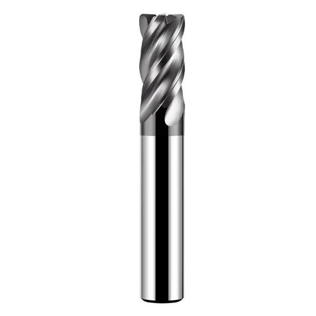
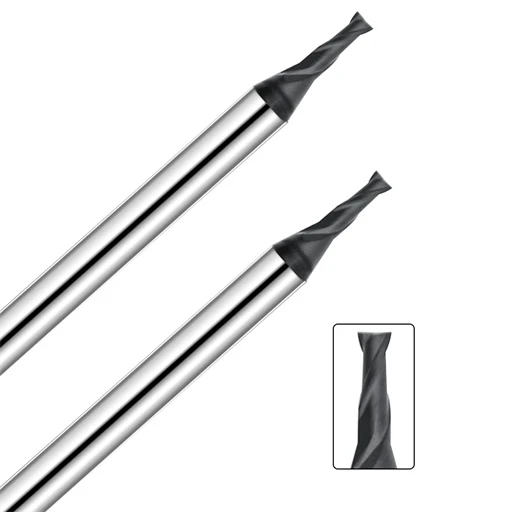
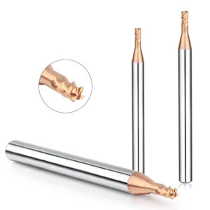
Tool selection for five-axis machining depends in part on the specific milling method (spot or side milling) being applied. Side milling requires a tool with sufficiently long radial cutting edges, such as solid carbide end mills or exchangeable head milling cutters. These milling cutters can be straight or tapered and have a variety of corner radii. There are several techniques for side milling: trochoidal, slice or profile milling. Tapered ball end mills offer greater stability than ball end mills, which require a smaller fit radius.
In trochoidal milling (a three-axis roughing technique), the tool cuts in a continuous spiral tool path, feeding radially in a confined space, with high material removal rates. The tool moves outward continuously with each cut, forming a groove or contour. Since the radial depth of cut is small, a larger depth of cut can be used and relatively small cutting forces are generated. Slicing (a three-axis semi-roughing/finishing technique) is similar to part rounding, and generally requires a high-speed, dynamically rigid machine tool. In addition, the cutting is performed with multiple passes at a small radial depth of cut, so that a larger axial depth of cut can be applied for large radii. Copy milling can be a 2D cutting process using only the side surface, or a 3D cutting process that forms the bottom surface for the tool radius. Copy milling also requires a high-speed, dynamically rigid machine tool and extremely high stability.

For Spot Milling
There are many tooling choices, depending on part features and surface quality requirements. Generally speaking, for larger open surfaces, round insert milling cutters or ball nose milling cutters are preferred. For pockets, tapered ball nose milling cutters with large tool overhangs are often the best choice, with the reduced diameter adapters provided by the modular tooling system ensuring maximum stability when tool accessibility is required.
Tool application for roughing is related to machine tool capabilities and part surface requirements, and larger effective tool diameters may be applied in three-axis machining. For semi-finishing, tool path strategies should mimic finishing strategies, and are usually most efficient in five-axis machining (sometimes using three-axis) to achieve the best machining results. The goal should be to leave a uniform machining allowance for the finishing operation.
For finishing, tool selection depends on the required surface quality and accuracy level, where simultaneous five-axis machining can be optimized by using different types of tools, specific to part features and finish. Round insert end mills are more commonly used, and ball nose end mills are suitable for cuts that require more demanding form and accessibility, such as closed pockets.
A Range of Various Milling Tools
Suitable for simultaneous and three-axis machining operations, depending on the degree of involvement of roughing and finishing. For example, large diameter round insert milling cutters are suitable for shallow large surfaces, which use relatively large radial cutting. When milling with round insert tools or end mills with large corner radius or round nose, it is best to apply appropriate lead-in and rake angles to ensure maximum performance and machining results. The chip thinning effect that can lead to high feed capabilities is a productivity factor that needs to be considered.
Ball nose tools are well suited for five-axis point milling, but accessibility and axis freedom are limited (three plus two axes), such as by part features or fixtures. These tools are generally solid carbide end mills or exchangeable head milling cutters, with short processing times and extremely high efficiency at high cutting speeds. Of course, they are also suitable for any three plus two axis machining operation.
Surface Quality During Five-axis Machining
It is partly a matter of stepover, which is related to the tool diameter. It is an important factor in the specific application because it affects the machining time and surface quality. Compared with ball-end cutters for conventional profile milling, the use of round insert milling cutters can significantly reduce cutting time. For round insert milling cutters, the relationship between stepover and diameter is a maximum of 1:2, and larger stepovers can reduce machining time but leave higher surface finishes. In this regard, ball end cutters do not provide the same productivity and machining conditions are also poorer. The tool will form a surface with certain high points depending on the feed per tooth and the cutting width, while the cutting depth affects the cutting forces and requires high tool stability. To achieve a smooth and uniform surface quality, tool inclination, feed value, cutting direction and tool clamping should be optimized to achieve the best balance.
In summary, each machining method and tool type has its specific advantages. The correct choice of tool and its application optimization can provide more machining possibilities and the opportunity to reduce the cost of five-axis machining. In addition, using good simulation software can significantly reduce the chance of errors and avoid wasting valuable production time testing new programs on the machine tool.