Common Forms and Working Methods of Vertical CNC Milling Machines
Vertical CNC milling machines are divided into small and medium-sized ones. Small CNC milling machines are generally vertical lifting table structures, that is, the main movement and feed movement of the machine tool are completed by the workbench; while the main movement of the medium-sized vertical milling machine in the Z direction is completed by the spindle box, and the feed movement in the X and Y directions is completed by the workbench. Since vertical CNC milling machines are generally three-coordinate machine tools, they are classified according to the number of controllable linkage coordinate axes.
Vertical CNC milling machines include three-coordinate linkage CNC milling machines and two-axis semi-coordinate linkage CNC milling machines. The parts commonly processed by vertical CNC milling machines include plane contour parts, space curved surface contour parts, and mold parts, etc. They can be used for plane milling of parts, plane cavity milling, shape contour milling, three-dimensional and more complex surface milling, etc.
Commonly Used Tools for Large Flat Surface Machining on Vertical Milling Machines:Carbide Indexable Face Milling Cutters
Definition of Face Milling Cutters
When machining large flat parts on vertical CNC milling machines, face milling cutters, also known as end milling cutters, are generally used. Face milling cutters have a large diameter cutter disc, a large cutting area, and high cutting efficiency. The main cutting edges of face milling cutters are distributed on the cylindrical and conical surfaces around the milling cutter, and the secondary cutting edges are distributed on the end face of the milling cutter.

Classification and Application of Carbide Face Milling Cutters
The most commonly used face end mill for vertical CNC milling machines is the carbide indexable face milling cutter, which is divided into 45° face milling cutter, 75° face milling cutter and 90° face milling cutter according to the main deflection angle of the blade. 45° face milling cutter is often used due to its low vibration, and can process planes, inclined surfaces, chamfered surfaces, etc. When this type of tool is used to process planes, the blade breakage rate is low and the durability is high.
The shock resistance of the 75° face milling cutter is greatly improved compared to the 90° face milling cutter, and the cutting is smooth and light. It should be used first in plane processing. This type of face milling cutter is a general-purpose tool with a wide range of applications and can be used for rough processing. The 90° face milling cutter can process both step surfaces and planes, but it has large vibration during processing, requiring the machine tool to have large power and sufficient rigidity. It is generally used for thin-walled parts processing.
How to Select the Diameter and Number of Teeth of Face Milling Cutter
When selecting the diameter of face milling cutter, the main consideration is that the power required by the cutter should be within the power range of the machine tool. The spindle diameter of the machine tool can also be used as the basis for selection. The diameter of the face milling cutter can be selected according to the formula D=1.5d (d is the spindle diameter). In mass production, the cutter diameter can also be selected according to 1.6 times the cutting width of the workpiece. Face milling cutters are divided into coarse teeth, medium teeth and fine teeth. Coarse teeth have fewer teeth, larger chip space, and greater tooth strength, which are suitable for rough machining; medium teeth milling cutters have stable cutting and are widely used; fine teeth milling cutters have more teeth, smaller chip space, and lower tooth strength, which are suitable for fine machining.

Commonly Used Tools for Contour Processing of Vertical CNC Milling Nachines:End Milling Cutter
Definition of End Mill
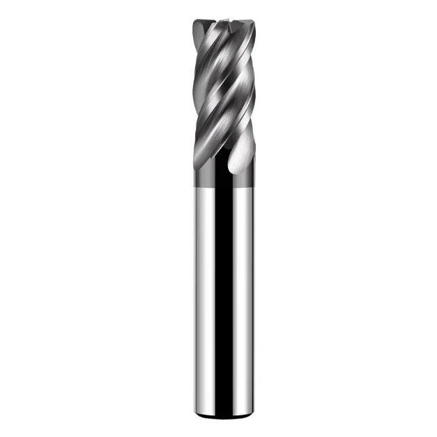
End mill is the most utilized tool on CNC milling machines. It can process planes, part contours, some open slots and forming surfaces, etc. The shape of the end mill is cylindrical, generally with more than three edges. The main cutting edge is distributed on the cylindrical surface of the milling cutter, and the end face is the secondary cutting edge. The shape of the end face of the milling cutter is center hole type or open type.
The Helix Angle of the End Mill and Its Function
End mills are divided into left spiral and right spiral, and the milling edge is also divided into left edge and right edge. The most common is right edge right spiral. The edge on the cylindrical surface of the end mill can be straight edge or spiral edge. However, the straight edge is intermittent cutting, with large vibration and poor surface quality; while the spiral edge is continuous cutting, each tooth gradually cuts in and out along the cutting edge, with very little vibration, thereby improving the stability of the cutting process and the surface quality of the workpiece. End mills with spiral edges are the most common.
The helix angle is generally 30° and 45°. For some workpieces with lower processing requirements, a 30° helix angle is generally used, with a large feed rate and a low speed. If the parts require higher quality, a 45° helix angle should be used, with a small feed rate and a high speed to improve the surface quality of the parts.
Selection of the Number of Teeth for End Mills
The chip groove of an end mill decreases as the number of blades increases, while the rigidity is the opposite. The more blades an end mill has, the better its rigidity is, and the rigidity affects the stability of the tool during milling. Therefore, end mills with 3 to 6 teeth are generally used for rough machining, while end mills with 5 to 10 teeth are used for fine machining.

Feeding of End Mill
When using end mill, there is a taboo, that is, it is generally not allowed to feed along the axial direction of the milling cutter, and it is recommended to feed along the radial direction of the milling cutter. However, if the processing method is changed, it is also possible to cut deep and feed along the Z direction. Common feeding methods are as follows.
- Feeding with drill bits and process holes. First, use a drill bit with a smaller diameter to process the process hole, and then use the end mill to perform vertical cutting and feeding in the Z direction.
- Using the spiral feeding method. CNC milling machines can achieve three-axis linkage spiral feeding, so that the Z-direction feeding and inner contour processing have a natural and smooth transition, and generally no processing marks will be produced. Therefore, this method is widely used.
- Oblique feeding method. The three-axis linkage oblique feeding method is used, and the end face edge of the end mill is used for cutting, thereby avoiding the center part of the tool from participating in the cutting. However, the disadvantage is that this feeding method cannot achieve a smooth transition between the Z-direction feeding and the inner contour processing, and it is easy to produce processing marks.
A New Member of End Mills – Carbide Spiral Tooth Milling Cutter
Carbide spiral tooth milling cutters have a larger diameter than ordinary end mills. A spiral groove is opened on the circumference of the milling cutter. Two or more carbide blades are installed in one groove, and the joints between adjacent teeth are staggered. The joints between blades in the same groove are used as chip grooves. This type of milling cutter has many blades that are staggered, shaped like mature corn, and is commonly known as a “corn milling cutter”. Because it is a spiral blade composed of multiple carbide blades, the “corn milling cutter” has high strength and high cutting force. It is mostly used for rough processing, can have a large back cutting amount and a large feed rate, and has a high milling efficiency.
A New Member of End Mills – Corrugated Edge Milling Cutter
The corrugated edge milling cutter has a corrugated blade, which can effectively reduce cutting resistance, reduce vibration, and increase milling efficiency. The corrugated edge milling cutter divides the narrow and long chips into thick and short broken chips through the corrugated edge, and the chip removal is smooth; the corrugated edge can increase the length of the cutting edge, which is not only conducive to heat dissipation, but also makes it easier for the cutting fluid to penetrate into the cutting area, with a good cooling effect, and can be used for fine processing.

Common Tools for Slots in Vertical CNC Milling Machines – Keyway Milling Cutters
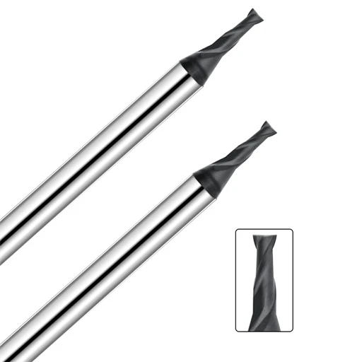
Keyway end mills are very similar to end mills in appearance, except that keyway milling cutters are two-edged tools, with no center hole on the end face. The end face teeth are opened from the outer circle to the axis, and the helix angle is generally 30°. The end face teeth have high strength, so the cutting edge on the end face teeth is the main cutting edge, and the cutting edge on the cylindrical surface is the secondary cutting edge. Unlike end mills, keyway milling cutters can be fed both axially and radially. Because the milling cutter has only two edges, its rigidity is not as high as that of end mills.
However, the accuracy and tolerance of the cylindrical diameter are very strict, and the overall accuracy of the milling cutter is relatively high. This also means that when using a keyway milling cutter to mill a closed round head keyway, it is necessary to select a milling cutter with the same diameter as the keyway, and use the diameter accuracy of the milling cutter to ensure the accuracy of the keyway. When the vertical milling machine tool is not complete, we can use a keyway milling cutter to process multiple contents, such as planes, grooves, contours, etc. This method is often used when students are just starting to learn milling machines and do not require very high machining accuracy.
Common Tools for Vertical CNC Milling Machines to Process Molds – Mold Steel End Mills
When processing mold cavities and three-dimensional molding surfaces on vertical milling machines, mold steel milling cutters are used. Mold milling cutters can be divided into cylindrical ball head milling cutters, conical ball head milling cutters, and conical flat head milling cutters according to the shape of the working part. Generally, mold milling cutters with smaller diameter specifications are often used, which can flexibly process some curved surfaces and inclined mold surfaces on the mold. The cutting edges on the cylindrical, conical, and spherical surfaces of the mold milling cutter are all main cutting edges. During milling, the milling cutter can be fed in the axial and radial directions.
Ball Nose End Milling Cutter
Carbide ball nose end mills use oblique milling or spiral interpolation milling to process cavities, which are suitable for high-speed processing. However, because the cutting speed of the ball head of the ball milling cutter is 0, it is generally not recommended to use the ball head milling cutter for axial feed. In order to ensure processing accuracy, the top cutting generally adopts a very small line spacing, so the ball head milling cutter is often used for the finishing of curved surfaces.
Conical Milling Cutter
The cone half angle of the conical end mill is 3°, 7°, 10°, 30°, etc. Conical mold milling cutters are widely used in the field of mold processing. As a forming tool, it can easily process bevels, with high production efficiency and simple programming. However, it is important to select the appropriate milling cutter according to the mold release angle and bevel requirements.
The Difference Between Ordinary End Mills and Drill End Mills
Ordinary end mills have a center hole in the center of the end face, and generally cannot be fed axially. Although drill mills belong to end mills, they have at least one pair of end face cutting edges connected together, that is, the cutting edges are through the center, and they have the functions of both drills and end mills, so they can be fed axially, but a lower cutting feed speed should be selected. In some CNC competitions, this new type of drill mill is often used, and the processing efficiency and processing quality are both high.
Selection of End Mills
In actual CNC milling, it is necessary to select appropriate tools according to the material, geometry, surface quality requirements, heat treatment status, cutting performance and machining allowance of the parts being processed, and the size of the tool should be adapted to the surface size of the workpiece being processed. For example: although both face milling cutters and end milling cutters can process planes, if the area of the plane is large, face milling cutters are preferred. In the processing of the peripheral contours of flat parts, end mills are generally used. When processing the surface of the blank or rough processing holes, “corn milling cutters” with carbide blades can be selected. For the milling of slots, both end mills and keyway milling cutters can be used for open slots or through slots. If it is a round head closed keyway, a keyway milling cutter should be used. If it is a round bottom slot, a ball head milling cutter should be considered.