Superhard carbide end mills have a unique advantage in the field of high-speed cutting, and their practical applications are increasing day by day. Among these tools, PCD (polycrystalline diamond) tools are the best choice for high-speed cutting of aluminum alloys and non-metallic materials, while diamond-coated tools are not only practical but also have a strong growth momentum. PCBN (cubic boron nitride polycrystalline product) tools are suitable for cutting cast iron, hardened steel, and other materials at higher speeds, and CBN (cubic boron nitride) coated tools are also expected to achieve major technological breakthroughs in the near future.
In order to ensure that high-speed cutting tools have a sufficient service life and low cutting force, the best tool geometry should be selected according to different workpiece materials. Compared with ordinary cutting, the rake angle of high-speed cutting tools is generally smaller or even negative, the back angle is slightly larger, and rounding or chamfering the tooltip is often used to increase the tool rake angle to prevent thermal wear at the tooltip. Since the rotary tool for high-speed cutting has to work at a very high speed, the centrifugal force problem is very prominent, so the tool body structure and blade clamping structure should be very reliable, and it needs to be strictly balanced on the dynamic balancer. It is best to be further installed on the machine tool and the spindle assembly for dynamic balancing.
The 7:24 taper connection is widely used between the tool and the spindle at ordinary speed, when rotating at high speed, because the solid taper shank cannot be “expanded” by the centrifugal force like the spindle hole, the gap between the two will cause the tool to swing in the taper hole, thereby causing the axial positioning error of the tool and destroying the dynamic balance of the structure. In order to overcome the disadvantage of poor high-speed performance of this connection, some connection methods suitable for high-speed cutting have been developed one after another.
CNC Tool Suitable for Processing Materials
To achieve high-speed cutting, tool material is the key. High-speed cutting materials mainly include cemented carbide, coated tools, metal ceramics, ceramics, cubic boron nitride and diamond tools. They each have their own advantages and are suitable for different workpiece materials and different cutting speed ranges. It must be noted that there is a compatibility problem between the tool material and the workpiece material pair, that is, one tool material has good performance with the workpiece material, but it is not ideal when processing another workpiece material. In other words, there is no universal tool material that can be used for high-speed processing of all workpiece materials.
High-speed cutting tool materials must be selected according to the workpiece material and processing properties. Generally speaking, ceramic tools, coated tools, and CBN tools are suitable for high-speed processing of ferrous metals such as steel. PCD tools are suitable for high-speed processing of non-ferrous metals such as aluminum, magnesium, and copper.
Ceramic tools have been used to process various cast irons, steel parts, thermal spraying and welding materials, nickel-based high-temperature alloys, etc.
Diamond milling cutters are suitable for processing non-metallic materials, non-ferrous metals, and their alloys. Due to the poor thermal stability of the diamond, it loses its hardness when the cutting temperature reaches 800°C. Because diamond and iron have a strong chemical affinity, iron atoms easily interact with carbon atoms at high temperatures to convert them into graphite structures, and the tool is extremely easy to damage. Therefore, diamond tools are not suitable for processing steel materials. When cutting non-ferrous metals, the life of PCD tools is dozens or even hundreds of times that of carbide tools.
Cubic boron carbide milling cutters are not only capable of rough and fine turning of hardened steel, bearing steel, high-speed steel, and chilled cast iron, but also capable of high-speed cutting of high-temperature alloys, thermal spray materials, carbide, and other difficult-to-process materials. CBN tools are one of the best tools for turning instead of grinding.
Commonly Used CNC Tools
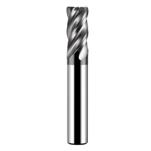
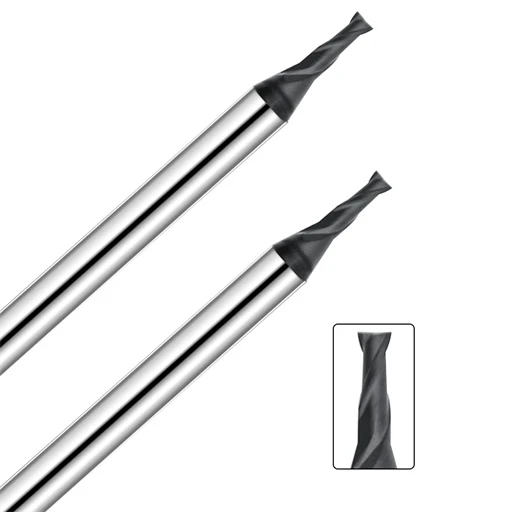
Carbide Milling Cutters
During face milling, due to the relationship between the milling cutter and the workpiece, size and position are important factors. When selecting a tool, the width of the workpiece determines the diameter of the milling cutter. For processing small parts, it is generally ideal for the tool diameter to be 30% larger than the workpiece, but the power and stability of the machine tool play a decisive role in many cases. Face milling often requires several passes to complete.
The number of edges of the milling cutter is another important factor in optimizing milling results. Having more than one edge cutting at any one time is an advantage, but too many edges cutting at the same time is a disadvantage. It is not possible for every cutting edge to be cut at the same time, and the power required is related to the number of cutting edges involved. The position of the milling cutter relative to the workpiece plays an important role in the chip formation process, cutting edge load, and processing results. When face milling, using a milling cutter that is about 30% larger than the cutting width and positioning the milling cutter close to the center of the workpiece, the chip thickness does not vary much. The chip thickness at the entry and exit is slightly thinner than when cutting in the center.
In order to ensure that a sufficiently high average chip thickness/feed per tooth is used, the number of teeth of the milling cutter must be correctly determined for the operation. The pitch of the milling cutter is the distance between the effective cutting edges. According to this value, milling cutters can be divided into three types – close-pitch milling cutters, sparse-pitch milling cutters, and extra-close-pitch milling cutters.
Also related to the chip thickness of milling is the main rake angle of the face milling cutter. The main deflection angle is the angle between the main cutting edge of the blade and the surface of the workpiece. There are mainly 45 degrees, 90 degrees and round blades. The direction of the cutting force will change greatly with the different main deflection angles: the milling cutter with a main deflection angle of 90 degrees mainly produces radial force, acting in the feed direction, which means that the machined surface will not be subjected to excessive pressure, which is more reliable for milling workpieces with weaker structures.
The radial cutting force and axial force of the milling cutter with a main deflection angle of 45 degrees are roughly equal, so the pressure generated is relatively balanced, and the power requirements of the machine tool are relatively low. It is particularly suitable for milling short-chip material workpieces that produce broken chips.
The milling cutter with a round blade means that the main deflection angle changes continuously from 0 degrees to 90 degrees, which mainly depends on the cutting depth. This kind of blade has a very high cutting edge strength. Since the chips generated along the long cutting edge are relatively thin, it is suitable for large feeds. The direction of the cutting force along the radial direction of the blade is constantly changing, and the pressure generated during the processing will depend on the cutting depth. The development of modern blade geometry has given circular blades the advantages of a smooth cutting effect, low machine power demand, and good stability. It is no longer an effective roughing cutter and is widely used in both face milling and end milling.
There are two ways relative to the feed direction of the workpiece and the rotation direction of the milling cutter. The first is down milling, where the rotation direction of the milling cutter is the same as the feed direction of the cutting. When the cutting starts, the milling cutter bites the workpiece and cuts off the last chip. The second is reverse milling, where the rotation direction of the milling cutter is opposite to the feed direction of the cutting. The milling cutter must slide on the workpiece for a period before starting to cut, starting with a cutting thickness of zero and reaching the maximum cutting thickness at the end of the cutting.
In three-face milling cutters, some end milling or face milling, the cutting force has different directions. In face milling, the milling cutter is just outside the workpiece, and the direction of the cutting force should be paid special attention to. In down milling, the cutting force presses the workpiece against the worktable, and in reverse milling, the cutting force makes the workpiece leave the worktable.
Down milling is usually the first choice because it has the best cutting effect. Down milling is only considered when the machine tool has thread clearance problems or there are problems that down milling cannot solve.
Ideally, the diameter of the milling cutter should be larger than the width of the workpiece, and the axis of the milling cutter should always be slightly away from the center line of the workpiece. When the tool is placed directly opposite the cutting center, burrs are very likely to be generated. The direction of the radial cutting force will change continuously when the cutting edge enters and exits the cutting. The machine tool spindle may vibrate and be damaged, the blade may break and the machined surface will be very rough. If the milling cutter deviates slightly from the center, the direction of the cutting force will no longer fluctuate, and the milling cutter will obtain a preload. We can compare center milling to driving in the center of the road.
Every time the milling cutter blade enters the cutting, the cutting edge will be subjected to an impact load, and the load size depends on the cross-section of the chip, the workpiece material and the cutting type. Whether the cutting edge and the workpiece can bite correctly when cutting in and out is an important direction.
When the cutter axis is completely outside the width of the workpiece, the impact force during cutting is borne by the outermost tip of the insert, which means that the initial impact load is borne by the most sensitive part of the tool. The cutter also leaves the workpiece with the tip at the end, that is, the cutting force acts on the outermost tip from the beginning of cutting to the end of cutting, until the impact force is unloaded. When the centerline of the milling cutter is exactly on the edge of the workpiece, the insert leaves the cut when the chip thickness reaches the maximum, and the impact load reaches the maximum during cutting in and out. When the cutter axis is within the width of the workpiece, the initial impact load during cutting is borne along the cutting edge at a distance from the most sensitive tip, and the insert exits the cut more smoothly during retraction.
For each insert, the way the cutting edge leaves the workpiece when it is about to exit the cut is important. The remaining material near the time of retraction may reduce the blade clearance to a certain extent. When the chip leaves the workpiece, an instantaneous tensile force will be generated along the front face of the insert and burrs will often be generated on the workpiece. This tensile force endangers the safety of the chip edge in dangerous situations.
The situation will be serious when the axis of the milling cutter coincides with or approaches the edge of the workpiece. Achieve a summary of good milling.
- Check the power and rigidity of the machine tool to ensure that the required milling cutter diameter can be used on the machine tool.
- The overhang of the tool on the spindle is as short as possible to reduce the impact load caused by the position of the milling cutter axis and the workpiece.
- Use the correct milling cutter pitch suitable for the process to ensure that there are not too many blades engaged with the workpiece at the same time during cutting to cause vibration. On the other hand, ensure that there are enough blades engaged with the workpiece when milling narrow workpieces or milling cavities.
- Ensure the feed rate per blade so that the correct cutting effect can be obtained when the chip is thick enough to reduce tool wear. Use indexable inserts with positive rake grooves to obtain smooth cutting effects and minimum power.
- Choose a milling cutter diameter suitable for the width of the workpiece.
- Choose the correct main deflection angle.
- Place the milling cutter correctly.
- Use cutting fluid only when necessary.
- Follow the rules for tool maintenance and repair, and monitor tool wear.

Carbide Brill Bit
Drill bits are the most widely used tools in hole processing tools, especially when drilling holes below φ30mm. Drills are divided into integral and indexable insert drills in terms of structure. Due to the pursuit of high production efficiency in the automotive industry, the application of shoulder and chamfer compound drills is becoming more and more extensive.
Many workpieces need to drill one or several holes, and most of these holes are now processed on CNC machine tools and machining centers. In principle, there are many different types of holes, and the most common difference between these holes is the fit clearance. These holes include threaded holes, holes with excellent fit requirements, pipe holes, and holes processed to remove weight. These holes are through holes or straight holes, and have different requirements for cutting tools and methods.
In the drilling process, in order to achieve satisfactory results in an effective way, four main factors need to be considered.
- The ratio of diameter to hole depth.
- The accuracy and surface roughness required for the processed hole.
- The type, quality and hardness of the workpiece material.
- The machine tool, especially the processing conditions and spindle speed.
These factors will affect the selection and application of drill types. In all machining processes, the stability of the workpiece, machine tool and process system is the most important. When considering what type of drill is suitable for the machining process, the drilling process plays a certain restrictive role. The smallest indexable insert diameter is 12.7mm.

Boring Tool
Boring tools are divided into integral, clamping, and adjustable types according to their structure. Adjustable types are further divided into fine-adjustment and differential types. Single-edge fine-adjustment boring tools and double-edge rough boring tools are commonly used in the machining of automobile transmission housings.
Rough boring tools use axial adjustment mechanisms to make the heights of the two edges completely consistent, achieve an ideal balance state, and prevent vibration. Feed thread is the lifeblood of the precision boring head. Some manufacturers use a paired production method to limit the tooth gap between the screw and the nut to a minimum and obtain the highest reliability. When boring the hole on the back, it is often necessary to reverse the workpiece or turn the worktable, which not only wastes time, but also makes it difficult to ensure coaxiality.
The precision boring head only needs to reverse the insert to perform reverse boring processing, which ensures accuracy and improves production efficiency. For holes with high precision requirements, the toolbar is required to have a high dynamic balance effect. The high-speed small hole precision boring head produced has poor mobile balance. The built-in balance block will move. According to the relevant data in the manual, the balance ring can be turned to the corresponding position to make the boring head balanced.
Thread Tapping
There are two ways of tapping on the machining center, high-precision automatic reverse tapping, with a maximum speed of 6000r/min, and rigid tapping without any compensation. These two ways of tapping have their own advantages and disadvantages, so they are selected according to the processing requirements. In mass production, due to the pursuit of high efficiency, the automatic reverse tapping will be beneficial to production, but it has a complex structure, many accessories, difficult maintenance, and expensive. At present, with the increasing use of CNC machining centers, rigid tapping will become more and more popular.