In actual production and processing, the processing programming of curved surfaces usually has two forms: automatic programming and macro program manual programming. Automatic programming often relies on CAD/CAM software, but due to the limitations of the underlying mathematical model of the surface constructed by this software and the approximation principle used by CAD/CAM software when generating curved surface tool paths, the software cannot intelligently judge when executing a true full circle or arc trajectory.
Therefore, the generated program is not formed by G02/G03 instructions, but by G01 point-by-point approximation. This not only causes the generated program instructions to occupy a large amount of space and make the machine tool slow to respond, but more importantly, due to the principle of linear approximation, the calculation error during the modeling period will be magnified during the processing process, thereby affecting the workpiece accuracy and surface quality.
In this context, taking the manual programming processing of the curved surface of a typical outer spherical surface as an example, this paper analyzes in detail the process of processing using cutting tools such as end mills, and verifies the effect of manual programming through practice. Through detailed practical operation and analysis, it is finally concluded that the rationality of the processing path has an important influence on the performance and quality of the actual processed workpiece. Reasonable selection and use of milling cutters, especially end mills, play a key role in improving the surface quality of workpieces. This processing analysis idea is not only of great guiding significance for actual production and processing, but also of great inspiration for CNC teaching.

Basic Knowledge of External Spherical Surface Processing
Selection of Commonly Used Tools for Spherical Surface Processing
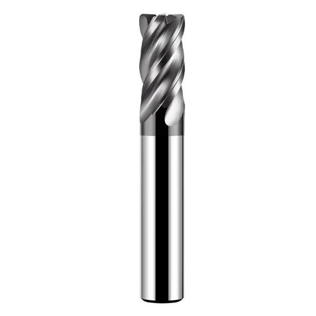
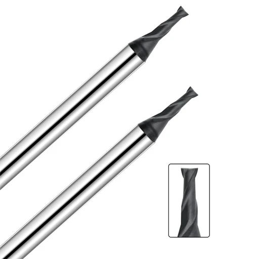
During rough processing, keyway milling cutters, end mills or ball end mills can be used. These tools are suitable for removing large amounts of material, especially ball end mills, which perform well when processing complex curved surfaces. In the finishing stage, ball end mills are usually used to obtain higher surface accuracy and quality. The unique shape of the ball end mill can evenly contact the workpiece surface, reduce cutting marks, and improve the final accuracy and finish of the workpiece.
Tool Path for Spherical Surface Processing
Generally, a series of concentric circles formed by horizontal planes cutting the spherical surface are used to complete the tool path. There are two types of feed control: feed from top to bottom and feed from bottom to top. Generally, feed from bottom to top should be used to complete the processing. At this time, the side cutting of the milling cutter is mainly used, the surface quality is better, the end edge wear is less, and the cutting force pushes the tool in the undercut direction, which is beneficial to control the processing size.
Feed Control Algorithm
- Determine the reasonable Z-direction feed amount based on the allowable processing error and surface roughness, and then calculate the radius of the processing circle based on the given processing depth Z, that is: r=sqrt[R2-z2]. This algorithm has a large number of passes.
- According to the allowable processing error and surface roughness, determine the angle increment of the two adjacent feed points relative to the center of the sphere, and then calculate the r and Z values of the feed points according to the angle, that is, Z=R*sinθ, r=R*cosθ.
Processing of Feed Trajectory
- For end milling, the surface processing is completed by the tool tip. When the tool tip moves along the arc, the tool center motion trajectory is also an arc of one diameter, but the position differs by one tool radius.
- For ball-end tool processing, the surface processing is completed by the ball edge. The tool center is a concentric sphere of the sphere, and the radius differs by one tool radius.

Spherical Surface Processing Scheme Proposed and Analyzed
Spherical Surface Processing Scheme Proposed
Layer-by-layer Processing Method
The layer-by-layer processing method is to use the macro program to set the cycle drive milling cutter. When the GO2/GO3 is used to mill the cone on the same plane, the Z direction remains unchanged. After the X and Y directions are milled and the X: Y direction movement stops, the milling cutter interpolates upward or downward along the Z axis. After reaching the specified value, the second cycle is performed until the entire cycle process is completed.
Spiral Interpolation Processing Method
The spiral processing method refers to the entire milling process from the beginning of the cutter to the end point. The milling cutter interpolates along a certain spiral line from the beginning of the cutter to the end point. The movement of the Z axis in the entire interpolation process gradually changes with the movement of X and Y.
Proposal Demonstration and Implementation
Analysis of Layer-by-layer Processing Method
The tool path in the whole processing process is as follows: under the control of the program, the milling cutter first moves to the processing starting point of the expected circle in the GO1 mode, stops for a while, and then performs arc interpolation in the GO2/GO3 interpolation mode. After the whole circle processing is completed, the Z axis moves up or down in the GO1 mode, and after the specified X and Y axes move in the GO1 mode again, and repeat the above steps until the processing is completed.
During the whole processing process, the movement of the Z axis is always independent and discontinuous. After processing a layer, due to the delayed reaction and sudden acceleration of the Z axis, the machine tool will “tremble”, and the consequences are often fatal. The light one will affect the workpiece accuracy or surface quality, and the heavy one will break the tool. In actual processing, the sudden movement of the Z and X/axes has obvious effects on the accuracy and surface quality of the workpiece.
Such consequences are mainly caused by the uncoordinated movement of the X, Y, and Z axes of the machining center. In order to overcome the quality problem, we adopted the commonly used arc cutting-in and arc cutting-out method for processing.
After adopting the arc cutting-in and arc cutting-out method, the surface quality has been significantly improved, especially the overcutting phenomenon caused by the movement of the X-axis has been completely improved, and the actual magnification simulation effect has been achieved. However, it can be clearly seen from the figure below that the step phenomenon caused by the incoordination of the X, Y, and Z axes has not changed at all.

Analysis of the Spiral Interpolation Method
In order to completely solve the above practical problems, we have proposed a spiral interpolation processing method. As shown in the processing diagram, the milling cutter starts from the lower end of the sphere and slowly rises along a spiral line. During the rising process, the three coordinate axes of the machine tool move simultaneously, and they are perfectly coordinated with each other.
Three-dimensional Spiral Machining Macro Program
Main program
Note:
- Angle #3 in the ZX plane is the independent variable to achieve 3D equal step machining;
- Since the initial value of angle #3 can be set, this program can be applied even if it is not a complete hemisphere;
- Practical processing has proved that the spiral interpolation processing method makes the processing smooth and reasonable, especially the surface roughness of the workpiece has been greatly improved. In addition, the spiral interpolation processing macro program has a simple structure, a short and sophisticated process and is easy to write. It is precisely because of the above program writing characteristics that the machine tool does not need to slow down when executing the program. Due to its smooth processing, it greatly speeds up the processing speed and improves production efficiency. This processing method fully meets the requirements of industrial production, and this improvement idea is fully in line with the development direction of the mechanical processing field.
Production practice shows that the reasonable arrangement of processing procedures and tool paths is crucial in CNC machining. The spiral interpolation method, with its smooth processing process and concise macro program, has excellent performance in improving workpiece accuracy, surface quality and production efficiency, which is in line with the development trend of mechanical processing and provides effective guidance for future CNC programming.