Analyzing, evaluating and rationally selecting different internal thread processing methods can help part manufacturers efficiently and economically produce high-quality threaded holes. Advantages and disadvantages of the five main internal thread processing methods: tapping, extrusion, milling, turning and grinding.
Tapping Processing of Internal Threads
Tapping is an effective and common method for many threading operations. It usually has the lowest initial cost, but it is not necessarily the most economical overall.
Tapping is a continuous cutting process in which workpiece material is removed by sequential cutting edges to obtain the final thread size in a single pass. Taps are manufactured specifically for the major, minor and pitch diameters of the thread. Since the taps must complete roughing and finishing in a single pass, a large amount of chips must be evacuated effectively and excessive pressure may be generated, resulting in problems with thread quality or damage to the tap.
Chip control is a major issue that cannot be ignored when tapping, especially when machining workpiece materials with lower hardness, higher viscosity, and the tendency to produce long strip chips. These strip chips have the potential to form a bird’s nest around the tap or accumulate in the chip flute, causing the tap to break in the hole. Aluminum, carbon steel and 300 series stainless steel are generally the most challenging workpiece materials for chip control.
Taps can process almost any workpiece material with a hardness below HRC50, and some tool manufacturers offer taps that can even process workpiece materials with a hardness as high as HRC65.
Hole diameter is another factor to consider. Most end users can only tap holes with a diameter less than 16mm. If the hole diameter exceeds 16mm, there will be a problem with whether the machine tool has enough power to turn the tap. When the hole diameter is less than 6.35mm, tapping is also prone to problems due to limited chip space and the lower strength of small diameter taps.
In addition, the internal thread length that can be processed by the tap can usually reach more than 3 times its diameter. For deep hole threads, taps are often faster than single-tooth thread milling cutters. As long as the chips can be successfully discharged from the hole, the depth of the tap can be tapped.
Because the diameter and pitch are fixed, one tap cannot process different screw sizes. In addition, due to the large contact area between the tap and the hole wall during tapping, and the high cutting force generated, the tap may break and get stuck in the hole, causing the workpiece to be scrapped. Tapping also requires a high lubricant to complete the process effectively.
Internal Thread Extrusion Processing
By transferring (rather than cutting) the workpiece material, extrusion taps can produce internal threads up to 4 times the diameter. Since no chips are produced, there is no need to worry about the formation of bird’s nests of chips. However, extrusion threads require that the workpiece hardness should be limited to less than about HRC40. In addition, the workpiece material must have good ductility because of the need to transfer material.
Extrusion taps are usually less than 19mm in diameter and can be as small as 0.5mm. The larger the tap diameter, the greater the friction generated during processing and the higher the power required for the machine tool.
Compared with cutting taps, extrusion taps are more rigid and less likely to break. The pressure acting on cutting taps is a tangential force through its polygonal surface, while the pressure acting on extrusion taps is a radial force toward the center of the tap, so it is much greater than the tangential force.
Compared with cut threads, extrusion taps are stronger because extrusion taps form threads by compressing (rather than shearing) the grain structure of the workpiece material.
Compared with cutting tapping, extrusion tapping requires a machine with greater torque and power, higher requirements for workpiece clamping stability, greater force required to transfer workpiece material than cutting workpiece material, and higher drilling accuracy requirements for screw holes.
In some industries, including the medical industry and the aerospace industry, extrusion tapping is not accepted. The thread pitch formed by extrusion tapping has defects, and the aerospace industry does not allow sharp points (U-shaped tooth profile) at the thread pitch. However, this defect does not affect the tensile strength of the thread, so it is not a reason to reject it for general-purpose parts.
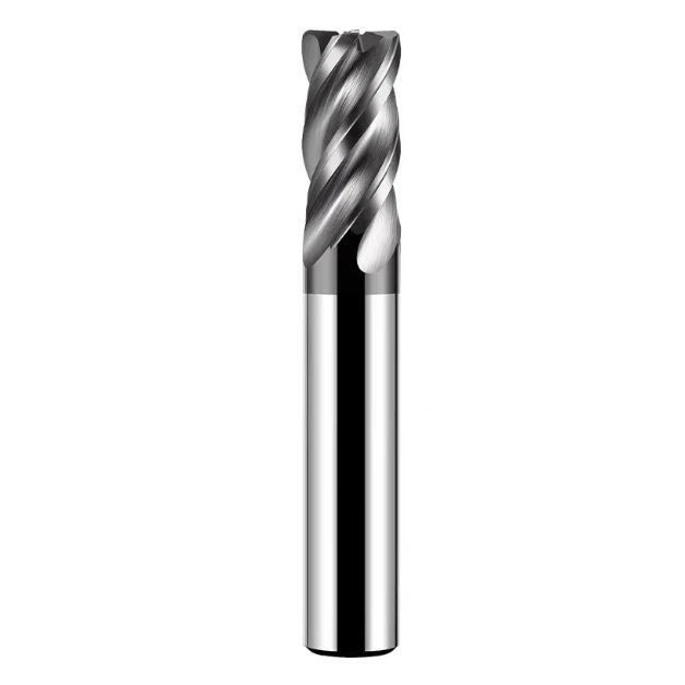
Milling Processing of Internal Threads
Thread end mills use helical interpolation to cut internal and external threads. Most CNC machines built in the past 10-15 years have thread milling capabilities.
Thread milling can be done with solid carbide thread mills or indexable insert thread mills (with steel shanks and carbide inserts). Multi-tooth thread mills produce full-depth threads in one rotation around the hole, while single-tooth thread mills have cutting edges on only one face and can only produce one thread at a time. However, most thread mills have multiple teeth.
Thread milling is suitable for machining workpiece materials with a hardness of up to HRC 65 and has excellent versatility. Thread mills with one or two different coatings are usually used to machine a variety of workpiece materials.
Chip control for thread milling is usually not difficult. Thread milling is an interrupted cut, which means that short, interrupted chips can be formed regardless of the chip characteristics of the workpiece material.
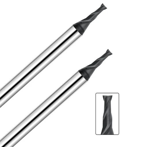
Thread mills cover a wide range of sizes, from threads as small as 0-80 (cutting diameter 1.524mm) to threads with the largest hole diameters. Generally speaking, the best hole depth for thread milling is controlled within about 2.5 times the hole diameter. The cutting force of thread milling is not balanced. If the milling length is too large, the large radial cutting force will form a large lateral pressure, causing problems such as milling cutter deflection, cutting edge chipping, and even small size milling cutters.
However, single-tooth thread milling cutters can process deeper screw holes, even up to 20 times the hole diameter. Since all cutting is done at the end of the milling cutter, there is no problem of tool deflection. Many users who produce oilfield equipment or large energy components need to use long-shank thread milling cutters. For them, milling multiple threads with a single-tooth milling cutter is slower, but it is still more cost-effective than investing $1,000 in a 250mm long tap.
Thread milling has many advantages. A single milling cutter can be used to process a series of screw holes with the same pitch and different hole diameters, while a single-tooth milling cutter can process screw holes with multiple pitches and multiple hole diameters. In addition, a thread milling cutter can be used to process both blind holes and through holes, and both right-handed and left-handed threads can be processed. Since the thread milling cutter has a flat bottom structure, it can also process a complete thread close to the bottom of the blind hole. Even if the end mill breaks, it is unlikely to cause the part to be scrapped. Finally, the thread milling cutter can also be combined with other hole processing tools to form a composite tool (such as a drilling, chamfering and thread milling composite tool).
However, compared with tapping, thread milling usually takes a longer cycle. Since thread milling requires a special processing program, some users may be reluctant to use this processing method. However, this program is not complicated and can be compiled using many CNC programming software.
Some companies still prefer tapping because they do not want the operator to intervene in the processing. Thread milling requires the operator to make some compensating adjustments to the machine tool. The diameter of the milling cutter will gradually decrease due to normal wear. In order to maintain the appropriate processing size, the operator must compensate for the tool wear through adjustments. The thread tolerance needs to be measured first, and then the processing parameters are adjusted according to the measured wear. The operator can only regularly test the thread with a gauge. If the test result is unsatisfactory, the tap needs to be replaced.

Internal Thread Turning Processing
Another way to produce internal threads is to turn them on a multi-axis machine or lathe with an indexable insert or a small, solid-body boring tool. This process can be done with either single-tooth or multi-tooth inserts. Multi-tooth inserts have multiple teeth on each cutting edge, with each subsequent tooth cutting deeper than the previous one. Using a multi-tooth insert reduces the number of passes required to complete the thread. However, multi-tooth inserts are more expensive, so they are more advantageous for high-volume production, not for low-volume production.
Internal threads can also be turned with a solid-body boring tool. When turning threads with a single-tooth tool, users can use either a full-profile or partial-profile insert (multi-tooth inserts only have a full profile), with full-profile inserts producing the full thread profile, including the crest (the insert cuts the minor diameter of the thread). With this insert, a separate insert is required for each pitch.
Full-profile inserts produce stronger and more accurate threads with fewer passes than partial-profile inserts because they can produce the major, minor, and pitch diameters of the thread at the same time.
Some tooth-shaped inserts have no crests (they cannot cut the thread diameter), and some tooth-shaped inserts have only one tooth, so different pitches can be produced by using different cutting depths. This thread has a very sharp crest arc, which reduces the strength of the coarse thread and takes longer to process.
The range of processing sizes for turning threads with indexable tools is very wide, from the largest diameter to screw holes as small as 6mm. Screw holes with a diameter of less than 6mm need to be processed with solid carbide tools, and the minimum hole diameter that can be processed can reach about 1.25mm. For large diameter holes, Vargus has processed large screw holes with a diameter of up to 0.9m on a vertical turret lathe that has been in service for about 100 years. There is no other way to process such large hole threads except turning. This old machine tool does not have helical interpolation function.
Thread turning tools with steel shanks are suitable for processing holes up to 3 times the hole diameter, while tools with carbide shanks can process holes 4-5 times the hole diameter.
Thread turning can also process a variety of workpiece materials, and threads can be turned on workpieces with hardness up to HRC50 or high-temperature alloys such as Hastelloy and Inconel. However, these materials are hard and abrasive, which shortens tool life.
Chip control is critical in internal thread turning, especially when turning blind hole threads. Users can use insert geometry to control chips, and use infeed methods (including radial infeed, flank infeed, flank modified infeed or flank alternating infeed) or reverse helical methods (thread formation direction away from the spindle rather than toward the spindle) to help chip evacuation.
Which infeed method to use depends on the processing conditions, but in most cases, it is beneficial to use modified flank radial infeed, so it can be the default preference. However, on almost all machine tools, if a parameter in the machining program is not changed, machining will be performed in radial infeed mode.
Grinding of Internal Threads
Thread grinding is a high-precision machining method and an effective choice for precision internal threads with strict tolerance requirements. Various internal threads, grooves, bearing raceways and other related part features can be machined on a grinder. Typical parts that can be machined with an internal thread grinder include thread ring gauges, roller nuts, ball screws, etc.
Internal thread grinding usually needs to be performed on a dedicated grinder. Generally speaking, in order to grind a thread with a precise tooth profile, the machine tool’s grinding wheel installation position must be tilted according to the helix angle of the thread, which requires a rotating axis, which most general-purpose grinders do not have. Sometimes the A-axis parallel grinding method can also be used, with a multi-tooth grinding wheel that has been modified (corrected its helical profile) directly inserted into the workpiece to grind the external thread, but internal thread grinding requires a single-tooth grinding wheel installed on the A-axis according to the helix angle.
The inner diameter size of the thread grinding with good machining economy is usually 10-25 mm. The rule of thumb for grinding deep hole internal threads is: the ratio of the length of the grinding wheel shaft to the diameter does not exceed 7:1. The main challenge in grinding deep internal threads is the helix angle versus hole diameter. As thread length increases and hole diameter decreases, grinding at high helix angles becomes difficult because the grinding spindle is more likely to collide with the workpiece.
Chip control for internal thread grinding involves flushing the grinding zone with coolant. Again, it is difficult to get the coolant to the grinding zone in the direction of the wheel rotation without obstructing the wheel and grinding spindle from entering the small hole, as the internal hole space is limited.
Internal thread grinding is highly accurate, allowing the wheel to be precisely contoured and re-contoured quickly as needed after the wheel is formed. In addition, internal thread grinding increases productivity. The wheel can be re-contoured to produce different thread shapes without having to change other wheels.
A good internal thread grinder must have several features: good rigidity and thermal stability, high axis motion accuracy, accurate closed-loop position feedback, and a temperature-controlled precision spindle.
How does a part manufacturer determine which internal threading method to use? Each processing method has its own advantages and disadvantages. If one processing method cannot obtain satisfactory results, other processing methods should be tried. When determining the internal thread processing process, it is important to consider what kind of machine tool you have and carefully evaluate the tool cost, processing cycle and tool life.