The types of milling tools mainly include end mills, face mills, flat mills, etc. Typical milling processes include milling planes, chamfers or edges, milling contours, milling slots, milling cavities, milling keyways, etc.
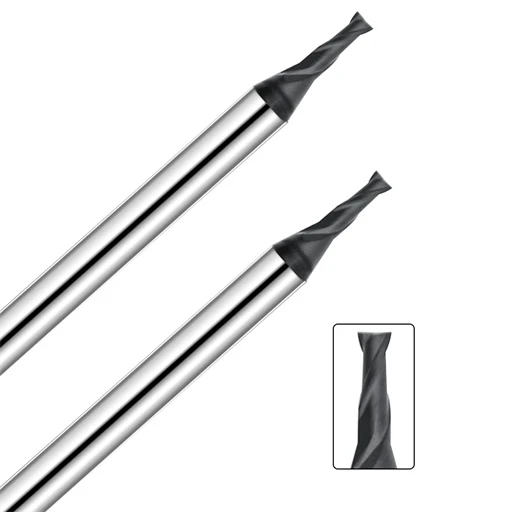
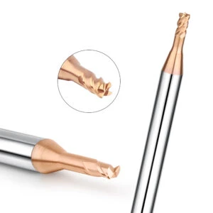
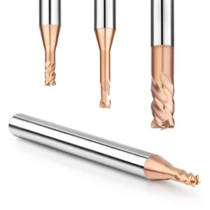
Several commonly used end mill design types include: square head double-edge end mills, which can perform vertical or side milling on the workpiece like a drill. Their end teeth extend to the center of the milling cutter, so they can perform plunge milling. Some three-edge end mills can also perform plunge milling. Both double-edge and three-edge end mills are suitable for processing non-ferrous metals. Ball-head double-edge end mills can be used for milling round bottom grooves or arc-shaped edges.
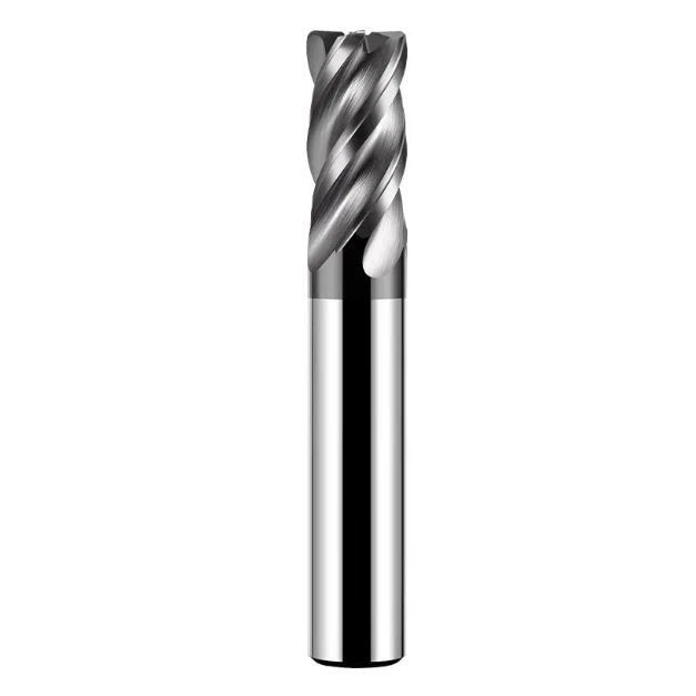
Composition and Names of Various Parts of End Mills
The shape of the end mill is basically composed of three parts: the blade part, the handle mounted on the machine tool, and the neck connecting the blade and the handle.
The blade part is the core component of the end mill, which consists of multiple cutting edges and is responsible for cutting the workpiece. The shape and size of the blade determine the processing performance of the end mill, including cutting depth, processing accuracy, surface quality, etc. The material of the blade is usually carbide or high-speed steel, which has good hardness, wear resistance and heat resistance.
The neck connects the blade and the handle, and plays the role of transmitting torque and supporting the blade. The shape and size of the neck are usually designed according to the size of the blade and processing requirements. The material of the neck is usually steel or carbide, which has good strength and rigidity.
The handle is the mounting part of the end mill, which is used to clamp the tool on the handle of the machine tool. The shape and size of the handle are designed according to the specifications of the handle of the machine tool. The material of the handle is usually steel or alloy steel, which has good strength and rigidity.
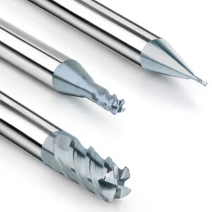
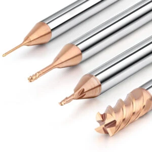
Number of Blades of End Mill
The rigidity and chip groove size of the end mill are very important. Generally, the chip groove of the milling cutter with fewer blades is enlarged and the chip removal is good. But on the other hand, the cross-sectional area ratio is reduced and the rigidity is reduced. Therefore, bending is easy to occur during cutting.
The Influence of the Number of Blades on Cutting Performance
Compared with 4-blade end mills, 2-blade end mills have larger chip grooves, but smaller cross-sectional area ratio and poor rigidity. Therefore, 2-blade end mills are suitable for groove cutting or drilling cutting where the chip groove requirements are greater than the overall rigidity requirements of the milling cutter.
Example: When processing deeper grooves (groove depth-to-width ratio greater than 1), if the chip groove of the end mill is small, the following problems are likely to occur:
- Due to chip blockage, the cutting torque will increase (in severe cases, the tool may break.)
- The cutting fluid is not easy to reach the cutting edge of the end mill, the cutting edge cannot be fully cooled and lubricated, and the chips near the cutting edge cannot be taken away by the cutting fluid, which will cause abnormal wear of the circumferential edge.
- The longer the cutting edge involved in cutting, the greater its cutting resistance, and it is easy to generate vibration.
Although the chip groove of the 4-blade end mill is smaller than that of the 2-blade end mill, the cross-sectional area ratio is increased, so the rigidity is improved, which is beneficial to reduce the bending of the end mill. For the milling side, because the chip blocking phenomenon is small, the size of the chip groove is not considered much, but the rigidity of the tool is more important. It is generally believed that the cutting resistance of the tool with more blades changes less, the tool has greater rigidity, is not easy to bend and deform, and the surface quality of the machined surface is good.
When milling complex workpieces on the milling machining center, the following issues should be noted when using CNC end mills:
Tool Selection
- Choose an end mill of appropriate size and material. The tool’s diameter, blade length, blade width, cutting edge angle and other parameters should be selected according to the requirements of the workpiece material, machining accuracy, surface finish and other requirements.
- Preferentially use a down milling cutter. When down milling, the cutting force acts on the root of the tool, the tool is not easy to vibrate, and the cutting is more stable.
- For deeper cavities or grooves, a long-edge end mill can be appropriately selected. However, care should be taken to control the extension of the tool to avoid excessive vibration.
Tool Installation
- Make sure the tool is properly installed in the tool holder. The tool shank should be in close contact with the inner hole of the tool holder without looseness.
- The extension of the tool should be as short as possible to reduce vibration.
- Use a torque wrench to tighten the nut of the tool holder to ensure sufficient clamping force.
Clamping of End Mills
Most end mills used in machining centers are clamped by spring clamps and are in a cantilever state when used. During the milling process, the end mill may gradually extend from the tool holder or even fall off completely, causing the workpiece to be scrapped. The reason is generally because there is an oil film between the inner hole of the tool holder and the outer diameter of the end mill shank, resulting in insufficient clamping force. End mills are usually coated with anti-rust oil when they leave the factory. If non-water-soluble cutting oil is used during cutting, a layer of mist-like oil film will also be attached to the inner hole of the tool holder. When there is an oil film on both the shank and the tool holder, it is difficult for the tool holder to firmly clamp the shank, and the end mill is easy to loosen and fall during processing. Therefore, before clamping the end mill, the end mill shank and the inner hole of the tool holder should be cleaned with cleaning fluid, and then clamped after drying.
When the diameter of the end mill is large, even if the shank and the chuck are very clean, the tool may still fall off. At this time, a shank with a flattened notch and a corresponding side locking method should be selected.
Another problem that may occur after the end mill is clamped is that the end mill breaks at the chuck port during processing. The reason is generally because the chuck has been used for too long and the chuck port has been worn into a cone. At this time, a new chuck should be replaced.
Vibration of the End Mill
The smaller the vibration of the end mill in normal processing, the better. Since there is a small gap between the end mill and the chuck, the tool may vibrate during processing. Vibration will make the cutting amount of the circumferential edge of the end mill uneven, and the cutting and expansion amount will increase compared to the original value, affecting the processing accuracy and tool life. However, when the width of the processed groove is small, the tool can also be vibrated on purpose to obtain the required groove width by increasing the cutting and expansion amount. However, in this case, the maximum amplitude of the end mill should be limited to less than 0.02mm, otherwise stable cutting cannot be performed. The smaller the vibration of the end mill in normal processing, the better.
When tool vibration occurs, consider reducing the cutting speed and feed speed. If both have been reduced by 40% and there is still a large vibration, consider reducing the cutting amount.
If resonance occurs in the processing system, the reason may be excessive cutting speed, low feed speed, insufficient rigidity of the tool system, insufficient clamping force of the workpiece, and factors such as the shape of the workpiece or the clamping method of the workpiece. At this time, measures such as adjusting the cutting amount, increasing the rigidity of the tool system, and increasing the feed speed should be taken.
Selection of Cutting Parameters
The selection of cutting speed mainly depends on the material of the workpiece to be processed; The selection of feed speed mainly depends on the material of the workpiece to be processed and the diameter of the end mill. The tool samples of some foreign tool manufacturers are accompanied by a tool cutting parameter selection table for reference. However, the selection of cutting parameters is also affected by many factors such as machine tools, tool systems, the shape of the workpiece to be processed, and the clamping method. The cutting speed and feed speed should be adjusted appropriately according to the actual situation.
When tool life is the priority factor, the cutting speed and feed speed can be appropriately reduced; when the chip separation condition is not good, the cutting speed can be appropriately increased.