After CNC machining technology was widely used in industry and machinery manufacturing, CNC milling became the main processing method for many complex parts. Through the combination of data programming and CNC equipment, precision parts materials are processed, which improves the production and processing efficiency of the current machinery manufacturing industry. However, in order to further adapt to the needs of the current market, improve higher quality parts materials, and analyze and study higher quality CNC programs, it is also a topic that technicians must pay attention to.
Therefore, in the cutting process, the changing factors that need to be controlled are not only the process of material parts, but also the size of the end mill tool, the tool path, the cutting amount and other factors, which will affect the quality and efficiency of material processing. Especially for some complex mechanical materials at present, there will be some complex curved parts, which need to be assisted by the part program in the CNC machining equipment and select reasonable cutting parameters. These are important factors to ensure the quality of the operation.
The Importance of Analyzing and Optimizing Cutting Parameters
In the history of mechanical engineering development, cutting databases in the mechanical manufacturing industry occupy a very important position. In recent years, in the process of my country’s industrial system development, a basic technical cutting database has been established in China. Usually, the initial cutting data settings are established through a lot of practice. The conditions required for the experiment are generally the basic conditions required for the current processing. Therefore, after the technical equipment is updated, the previous parameters need to be re-optimized and designed. Therefore, once the cutting database is built and generated, it is more difficult to update. Some previous databases have to face data aging and cannot be used. If the cutting data cannot be updated with the update of technical equipment, it will not be able to guide the production and processing of material parts, and it will also cause a lot of resource waste.
With the development of the market, the technical equipment inside many manufacturing factories is also constantly innovating and improving. If the corresponding cutting parameters are not optimized and set synchronously, it will affect the efficiency and quality of subsequent material production and processing. Based on the above factors, optimizing the selection of mechanical equipment and the setting of cutting parameters will be the problems that manufacturing enterprises must face, and the important role and significance of them are.
First, by reasonably selecting mechanical processing equipment and optimizing cutting parameters, technicians can use matching data programs while updating equipment technology to ensure that the efficiency and quality of production and processing will not be affected. Second, in the process of data programming considering cutting parameters, the data model and algorithm can be explored and optimized simultaneously, making the relationship between programming data and cutting processing clearer. Third, optimizing data models and cutting parameters can effectively reduce the cutting time of machine tools and improve production and processing efficiency, while also reducing the waste of processing materials.
In general, cutting parameters are resources that need to be continuously optimized and changed with the innovation of technical equipment. At the current stage, the domestic industrial system is facing the stage of industrial upgrading, and there are many cutting parameter optimization problems that need to be solved. Many key technical nodes also require technicians to continuously explore and optimize. Only through long-term research and analysis can the effectiveness of data parameters be gradually improved.
Research Status of Equipment Selection and Cutting Parameters
In the processing of metal composite materials, cutting has become the most feasible processing method at this stage. In many factories, the amount of processing using cutting has accounted for half of the workload, and most material parts are produced and processed by cutting. However, the quality and efficiency of current cutting processing is still an important research content that needs to be optimized and solved.
Reasonable selection of cutting data and equipment can improve efficiency. In some traditional parts processing, when it comes to batch production, process tests are required to formulate specific cutting parameters. For single-piece parts products, technicians’ own experience and operation are required to test cut. Whether effective finished products can be obtained in the end depends on the level of technicians. In the process of these tests, a large number of defective products and waste products will inevitably appear, so a large number of factories are currently studying how to optimize the use of UG, CAM and other software.
Reasonable determination of cutting parameters will directly affect the factory’s cost consumption, production efficiency, quality, profit, etc., but the setting of cutting parameters is often subject to many internal and external factors, such as processing requirements, material properties, tool selection and use, machine tool accuracy and performance, technical personnel’s professional level, etc. These will directly affect the design and formulation of cutting parameters. Therefore, in the process of optimizing the setting of cutting parameters, technical personnel are required to establish a data model to optimize the parameter setting, which mainly involves three aspects of parameter setting, namely design variables, objective functions, constraints, etc. At present, the commonly used methods for optimizing cutting parameter settings are linear programming, coordinate rotation method, graphical method, etc.
Optimization of Equipment Selection and Cutting Parameter Settings in Material Processing
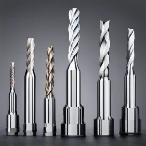
Select Cutting Tools According to the Material’s Processing Profile
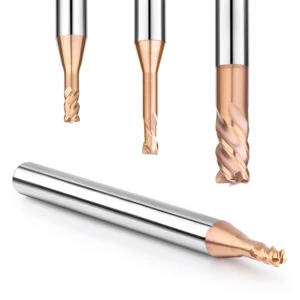
If there is a concave machining surface in the metal material to be processed, a ball end mill should be selected in the finishing or semi-finishing to ensure a good machining surface. If it is rough machining, a flat end mill can be selected. If the machining surface is a convex surface, a round nose end mill needs to be used during the rough machining process. Because the geometric conditions of the fillet milling cutter are often more suitable than the flat end milling cutter. In the process of finishing, the radius of some tools used should be smaller than the fillet radius of the machined parts, especially at the corners of some parts. It is necessary to select a tool with a radius lower than the corner radius to interpolate the arc. This can ensure that some straight line interpolation processes will not have over cutting problems and cause material damage.
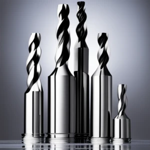
The Selection of Cutting Tools Should be Based on the Principle of Large to Small
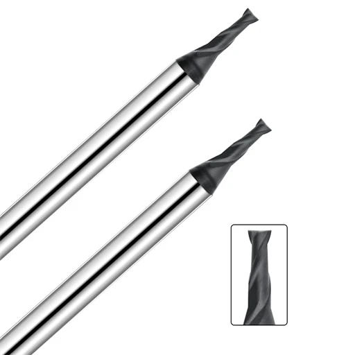
For some complex parts, there will be many surface types, especially in the processing of some complex curved parts, a cutting tool is often unable to complete the entire part processing process, so in the selection of tools, try to choose tools with larger diameters, whether for finishing or roughing. This is because during the processing, the smaller the radius of the tool, the longer the processing path it needs to go through, which reduces the processing efficiency, and the tool with a smaller radius will also wear more.
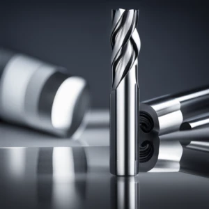
Selection of face milling cutter. Face milling cutter is one of the most widely used tools, and its cutting amount is also the largest category of all tools. Its main advantage is that the cutting amount is large, so the processing efficiency is higher than other tools, and the surface of the processed material parts is relatively smooth, not too rough, and it also has the characteristics of high temperature resistance, so it is often used in hexahedrons and some large-face step material workpieces. If you use a face milling cutter to process some rough molds or mold cavity grooves, you should be careful not to use vertical cutting, oblique feeding, or spiral feeding methods for processing. Such feeding methods are more likely to damage the machine spindle, resulting in a shortened service life of the internal equipment of the machine, so it is generally necessary to select a side feeding milling method from the outside of the workpiece.
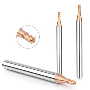
Rough end mill. Rough end mills are generally used for workpiece forming. The main advantages are large cutting volume, deep cutting, and small resistance encountered during cutting. In most cases, they are used for milling steps, sockets and other workpieces.
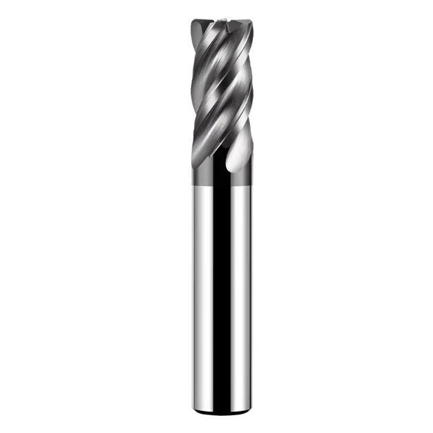
Fine end mill. Fine end mills are generally used for fine processing. After processing with this type of tool, the surface of the workpiece is generally smoother and flatter, and the dimensional accuracy of the processing is higher. When some workpieces are about to be formed as the final process of processing, this type of tool is used to maximize the appearance and reasonable size of the processed parts, so fine end mills are generally used for fine processing of workpieces such as mold cores and mold bases.
Discarded end mill. This type of tool is generally used at high speed and high rate. It is a common processing method in light cutting. Generally, this type of tool is used more in NC courses. The tool itself is also divided into two types: coarse and fine. The coarse tool is generally used for escaping, and the fine tool is used for finishing the bottom surface of the workpiece.
Consideration of cutting amount. The cutting depth generally refers to the surface layer of the cutting workpiece in one feed. In most cases, millimeters are used as the depth unit. Usually due to the problems of machine tool rigidity and tool strength, the cutting depth is also considered according to the brand of the tool and the properties of the material parts during the processing of some material parts. In the process of cutting, some positions need to be reserved, about 0.4mm~1.2mm. Even in the process of finishing, the machining allowance will be reserved according to the brand and dimensional accuracy of the tool, which is about 0.02mm~0.05mm. In the process of finishing, it is necessary to pay attention to the processing principle of trimming the bottom without trimming the edges and trimming the edges without trimming the bottom.
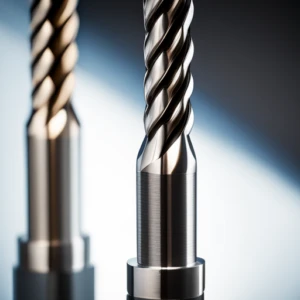
Try to Choose Round nose End Mills During Rough Machining of Parts
Due to the characteristics of corner radius milling cutters, the blade angle can vary within a range of 90° when in contact with the part during the cutting process. A more continuous cutting force change can be used within the processing range, making the processing process more flexible. This is more conducive to improving the processing quality and ensuring the extension of tool life. Moreover, when using a round nose milling cutter during rough processing, the cutting conditions will be better than when using a ball nose milling cutter.
Optimization of Cutting Parameters Settings
The above has made it clear that the setting of cutting parameters is important for material part processing, especially for processing quality and efficiency. For example, in CAM software, the cutting parameters that need to be controlled are mainly about spindle speed, depth and width of tool cutting, etc.
etting of spindle speed. When controlling the spindle speed of a machine tool, the cutting speed is generally used for calculation and setting. The commonly used calculation formula is n=1000VC/πd, where d represents the diameter of the tool and vc represents the cutting speed. In the processing process, the selection of the cutting speed of the tool is often related to the durability of the tool. Once the materials, tools and processing structures used are clear, the cutting speed will directly become a factor affecting the durability of the tool, and an inappropriate cutting speed will directly reduce the service life of the tool. Especially in the finishing process of some material molds, it is necessary to avoid changing the tool during processing, otherwise it will affect the processing quality.
Various factors of feed rate in spindle speed: T=0.3D, T refers to the depth of descent of each tool in the Z axis. P=0.7D, P refers to the feed rate of each tool. Below T=R2=0.2mm, below R3=0.5mm, P=0.1D, so the final speed F=S*FZ*Z, FZ refers to the cutting amount per tooth, Z refers to the number of teeth, and F refers to the feed rate. Of course, the formula may be different in different programs. Some formulas show: F=nzf. In this formula, n refers to the spindle speed, z refers to the number of milling cutter teeth, and f refers to the feed per tooth. The setting of the feed per tooth is also considered according to the properties of the material, the quality and structure of the tool. Usually, the higher the strength of the workpiece, the smaller the feed per tooth. The technicians need to consider the parameter setting based on the actual processing needs.
Processing feed speed and tool cut-in. In terms of the selection of feed speed, such factors will directly affect the surface smoothness and precision of the parts after processing. The commonly used parameter design formula is f=nzf, where n represents the spindle speed, z is the number of milling cutter teeth, and f is the feed per tooth. There are many factors that affect the feed per tooth, mainly considering the tool material, milling cutter structure, and mechanical properties during the processing. If the strength of the material workpiece itself is more reliable, the required feed per tooth will be smaller. For some alloy milling cutters, their hardness reliability is higher than that of traditional steel milling cutters. If the requirements for accuracy and surface processing precision in material processing are higher, the setting of feed rate should focus on appropriate reduction.
Setting of cutting amount and step width. When CNC machining is used for some curved surface part materials, due to the different curvatures and radii of different part surfaces, the processing is very complicated and cumbersome, so it needs to be distinguished from the plane milling processing method. For example, in the process of processing some blank materials, try to use the layered cutting method, in which each layer uses a circular cutting or a spiral cutting method between layers. The angle should be less than 15°, the cutting depth needs to be controlled within 10% of the total length of the material, and the step distance of each layer of material needs to be set according to the size of the mold, usually controlled at about 70% of the tool diameter.
Choose a smaller cutting amount and a fast feed rate to ensure the quality of the material workpiece. For some complex material models, choose appropriate tools to carry out processing separately to ensure processing efficiency. The size of the cutting amount will also be affected by the workpiece, machine tool, and tool. Therefore, when choosing actual processing, it is necessary to consider that these tools should try to meet the needs of processing technology and rigidity.
When processing, the maximum cutting amount should be selected to ensure processing efficiency and quality. In addition, in order to ensure that the processing accuracy and the surface roughness of the parts meet the processing requirements, it is necessary to ensure a certain processing allowance. In some rough processing processes, the removal of the allowance is usually done by layer cutting, and then designed by CAM programming. This requires technicians to consider the specific cutting depth and maximum step width of the tool according to the situation. These data settings will directly affect the forming shape of the workpiece.
In the process of finishing, it is necessary to choose the appropriate cutting depth, and the setting of the cutting depth usually needs to take into account the surface roughness of the part. When using CAM programming, the general program provides two types of parameters to control the surface roughness, mainly about the residual height and step width. When programming, controlling the step width will further affect the surface roughness of the machined part. Usually, the smaller the step width, the smaller the surface roughness of the final formed part. However, due to the setting problem, the processing efficiency will be reduced, further extending the processing time.
Therefore, in actual processing, it is also necessary to consider the processing requirements and try not to set the step width too low. In the actual processing process, you can adjust to the semi-finishing method or use the finishing method to adjust the tool path to improve the surface state of the machined part. If the residual height is used to control the roughness of the machined surface of the part, the layout width will be automatically adjusted according to the shape of the workpiece.
Consideration of cutting speed. Cutting speed generally refers to the linear speed of the spindle tool when it rotates. The setting of cutting speed will be affected by the quality of the tool itself and the properties, durability, processing conditions and cooling conditions of the material parts. Generally, the cutting speed of high-speed steel is set at 20m/min~130m/min, the cutting speed of cemented carbide is generally set at 20m/min~160m/min, and the cutting speed of tungsten steel is generally controlled at 30m/min~150m/min. Depending on the properties of the material, the cutting speed will also be appropriately adjusted according to the actual situation.
Feed rate control. Generally refers to the distance that the tool moves along the feed direction in one minute, and the factors affecting the feed rate are mainly tool strength, machine tool performance, processing accuracy control and part surface smoothness. The superposition of these factors will also directly affect the control of the feed rate. Usually, the feed rate of machining machine tools is controlled at 30mm/min~1400mm/min. Some high-speed and high-performance machining machine tools can reach 150mm/min~2000mm/min.
In general, in the process of parts material processing, the factors that affect cutting parameters are mainly cutting tools, machine tool performance, workpiece environment, etc. Each factor will have different degrees of influence on cutting parameters. This article summarizes some of the factors that affect cutting parameters, analyzes factors such as cutting tools and workpiece materials, and clarifies their specific impact on cutting parameters. In the future, mechanical processing will continue to develop in the direction of high precision and high efficiency. While continuously optimizing technical equipment, it is also necessary to focus on the establishment and use of cutting data models to promote the improvement of material parts processing quality and efficiency.