


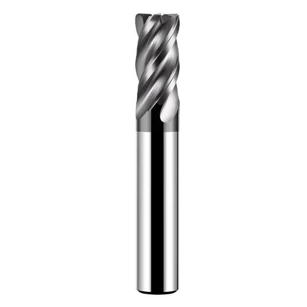
During a technical consultation with the chief process engineer at a long-established German mold manufacturer, he showed us several worn-out roughing endmill for steel tools. Every single cutter exhibited severe micro-chipping and thermal cracks on the cutting edges. They had been machining an H13 die-casting mold (HRC 48–52) for an automotive headlight bracket. Machine spindle load spiked past 85%, chip evacuation failed, and tool life dropped to just one-third of expectations.
This is by no means an isolated incident. Over the past 15 years of providing technical support and custom carbide rough endmills to manufacturing clients in North America and Europe, we have frequently seen improper roughing strategies lead to skyrocketing costs and spindle damage.
When machining pre-hardened and tool steels like P20, 718H, or H13, many machine shops still rely on standard flat-bottom end mills or blindly copy catalog parameters. The result is usually rapid tool wear from incorrect roughing endmill speeds or severe machine chatter caused by excessive cutting forces. For mold and die shops—where high Metal Removal Rates (MRR) and strict lead times dictate survival—this profit drain is unacceptable.
As cutting tool manufacturers and field application engineers, we know that chip breaker geometry, substrate thermal-shock toughness, and coating adhesion (like nACo or AlTiN) dictate tool performance in deep cavity roughing. Whether you buy a wholesale rough endmill directly from the factory or seek the best endmill for roughing steel, matching parameters to tool geometry is critical. This is why more overseas shops now source high-value, precision-stable china rough endmill options.
Is the roughing endmill in your shop slicing through metal with high efficiency, or is it quietly eating away at your spindle’s lifespan and your profits?

The Real Pain Points of Roughing Mold Steel: Why Do Standard End Mills Chip on P20 and H13?
If you walk through major mold manufacturing facilities, scrap bins are routinely filled with flat-bottom end mills that chipped during roughing. Operators often use standard solid carbide end mills to clear main cavities, assuming that simply reducing the feed rate will suffice. However, this approach fails on P20, 718H, or hardened H13. Straight-edge geometries cannot withstand continuous impact, causing heat to build up at the tip until micro-chipping occurs.
During on-site diagnostics for clients, we frequently resolve spindle alarms and thermal overload caused by improper tool selection. Mold roughing is not just scraping metal away; it is a rigorous test of impact resistance, red hardness, and chip control. Switching to a dedicated roughing endmill for steel prevents wasted tool budget and protects your expensive machine spindles from long-term damage.
Fundamental Differences Between Mold Roughing and Standard Part Machining: Deep Cuts, Pre-hardened Steel, and High Stress
Machining aluminum or mild steel parts typically prioritizes high cutting speeds, light cuts, uniform allowances, and easy chip removal. In contrast, mold roughing involves pre-hardened steels like P20 (HRC 30–32) and 718H (HRC 36–40), as well as hardened H13 (HRC 48–52). These materials work-harden quickly, and mold blanks often contain hard cast skins or residual forging stress that cause cutting forces to spike violently upon tool engagement.
During heavy-duty cuts with large axial depths (Ap) and full radial widths (Ae), standard straight-edge cutters generate long, continuous ribbon chips. These chips fail to break inside narrow mold cavities, causing re-cutting, heat spikes, and thermal cracks. A specialized roughing endmill changes chip morphology, disperses localized stresses, and keeps high-volume material removal safe and predictable.
Key Cutting Parameters for Selecting Carbide Rough Endmills for P20, 718H, and H13 Mold Steels
Selecting carbide rough endmills for steels above 50 HRC requires balancing substrate toughness rather than focusing solely on raw hardness. While ultra-hard tungsten carbide sounds ideal, excessive hardness increases brittleness during interrupted cuts and deep-cavity overhangs. We recommend a balanced substrate with a 0.4–0.6 μm grain size and 10–12% cobalt, paired with AlTiN or nACo nano-coatings to maximize wear and chipping resistance.
Flute geometry is equally critical. Machining P20 and 718H requires generous chip gullets for smooth chip evacuation. For hardened H13, sacrificing a bit of chip space for a thicker, stiffer core prevents tool deflection under heavy loads. Choosing geometry based on material hardness remains our core guiding principle when configuring standardized tooling for customers.
Workshop Test Data: Why Wave-Edge Roughing Endmills for Steel Significantly Reduce Spindle Load
To evaluate how tool geometry affects machine load, we conducted dynamometer tests on H13 mold steel. We compared a standard straight-edge cutter against a wave-edge cutter using identical parameters: 12mm diameter, 6mm axial depth of cut, and matching feed rates. The test data showed that the wave-edge design reduced lateral X/Y-axis cutting resistance by 32% to 38%, accompanied by a significant drop in spindle load current.
This load reduction comes directly from the wave-shaped chip-breaker geometry. The wave edge chops wide, continuous chips into small, curled segments, reducing friction between the chip and the rake face. Using a wave-edge roughing endmill for steel dissipates chatter across the crests and troughs of the cutting edge, extending tool life while keeping machining operations smooth and stable.
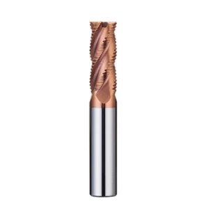
How to Choose the Best Endmill for Roughing Mold Steel?
Overseas shop supervisors often ask us why tools labeled “mold-specific” show a threefold price difference, yet perform vastly differently on the floor. Many shops fall into the trap of focusing solely on brand or price while ignoring how physical tool properties match their specific operating conditions. Finding an efficient tool for high-load mold roughing requires analyzing three core dimensions: substrate material, coating, and flute geometry.
When assisting shops with process optimization, our criterion is never “which tool costs the most,” but “which tool maintains the longest effective cutting time.” Selecting the best endmill for roughing steel is a systematic balancing act between rigidity, heat resistance, and chip evacuation. Understanding the engineering logic behind tool structures allows you to make rational selection decisions across mold steels of varying hardness.
Carbide Substrate and Grain Size: Why Standard Carbide Fails at Roughing Hardened Mold Steel
Many machinists assume higher carbide hardness is always better. However, using standard K10 or coarse-grained tungsten carbide on hardened mold steel above 50 HRC causes instant edge chipping. Standard carbide features coarse grains and uneven cobalt distribution. Under interrupted cuts and heavy impacts, micro-cracks form easily and propagate rapidly, making insufficient toughness a fatal flaw.
When developing tools for hardened steel, we prioritize ultra-fine-grained substrates (0.4–0.6 μm) and strictly control cobalt content between 10% and 12%. This microstructure maintains high red hardness while imparting excellent impact toughness to the cutting edge. When machining hardened H13 or S136, only a roughing endmill for steel that balances hardness and toughness can withstand heavy cutting forces.
Real-World Coating Comparison: Wear Resistance of nACo vs. AlTiN Coatings in Dry Machining of 50+ HRC Mold Steels
In dry machining of mold steels above 50 HRC, the coating acts as a protective shield. Many shops rely on traditional AlTiN coatings, which perform reliably at moderate temperatures. However, high spindle speeds and deep cuts push temperatures past 800°C. At this point, AlTiN surface hardness drops rapidly and oxidation resistance diminishes, causing severe flank wear and flaking.
In contrast, nACo nanocomposite coatings offer clear advantages for dry cutting. At high temperatures, nACo forms a dense, silicon-rich protective film with heat resistance exceeding 1100°C and hardness up to 40 GPa. Customer testing shows carbide rough endmills with nACo coatings deliver over 40% better wear and thermal crack resistance than traditional coatings, making them ideal for high-load dry milling or MQL.
Flute Count and Chip-Breaker Design: Selection Guidelines for 4-Flute vs. 5-Flute Carbide Roughing Endmills in Deep Mold Cavity Roughing
Deep cavity roughing creates a constant conflict between chip clearance space and tool rigidity. Engineers often struggle to choose between 4-flute and 5-flute designs. 4-flute cutters feature larger chip gullets that prevent chip packing. However, during long-overhang deep cavity work, their thinner core makes them prone to deflection and chatter. Conversely, 5-flute cutters offer a thicker core and superior rigidity, but poor chip evacuation can cause catastrophic tool failure.
Our rule of thumb is straightforward. For medium-to-shallow cavities where chip removal is difficult, prioritize 4-flute roughing cutters with wavy edges to leverage large gullets. For deep cavity sidewalls with small radial step-overs (Ae), a 5-flute design with fine-pitch wavy grooves is superior. Combining a 5-flute rigid core with wave-edge chip breaking ensures stable, high-volume material removal.
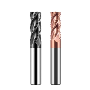
Practical Parameter Tuning: A Shop-Floor Guide to Optimizing Roughing Endmill Speeds and Feeds
Operators often blindly apply the recommended parameters printed on tool packaging, resulting in rapid tool wear or severe spindle noise. Catalog values assume ideal, rigid machines and simple test blocks. Real mold roughing involves complex variables like spindle taper, tool overhang, and coolant angles. Cutting parameters must be fine-tuned based on real-world shop conditions.
We establish dynamic parameter adjustment logic when providing technical support to field engineers. The goal of parameter optimization is not chasing maximum RPM, but maximizing the Metal Removal Rate (MRR) while keeping tool life controllable and machine spindles safe. Once mastered, your roughing endmill speeds become flexible variables optimized in real-time based on material hardness and machine capabilities.
Moving Beyond Manuals: Precisely Matching Roughing Endmill Speeds to Mold Steel Hardness (HRC 30–55)
Every 5-point increase in steel hardness drastically changes cutting temperatures and tool stress. When machining pre-hardened steels like P20 (HRC 30–32), we set high surface footage (SFM) to leverage carbide heat resistance. However, when switching to hardened H13 (HRC 48–52) or S136, maintaining high speeds accelerates diffusion wear. You must lower cutting speeds and rely on feed per tooth (IPT) to carry away heat.
Our shop tests prove that for hard mold steels (50+ HRC), moderately reducing roughing endmill speeds while using high-pressure air blast can more than double tool life. Never hesitate to lower spindle RPM. Provided your feed rate is properly balanced, the thermal control benefits far outweigh any minor loss in cycle time.
The Golden Ratio of Feed per Tooth (IPT) to Axial/Radial Depth of Cut (Ap/Ae): Preventing Tool Burning and Chatter
Engineers often fall into two extremes: using heavy axial depth with tiny feed rates that cause chip welding, or shallow depths with excessive feeds that trigger severe machine chatter. We recommend determining depths of cut based on force distribution. In traditional heavy cutting, axial depth (Ap) should equal 0.5–1.0x cutter diameter, while radial width (Ae) stays between 0.5–0.7x diameter to distribute force evenly along the edge.
To prevent tool burning, feed per tooth (IPT) must keep chips thick enough to absorb heat rather than rubbing the material. If cutting noise turns high-pitched or chips turn dark blue, cutting zone temperatures are too high. Slightly reducing Ae while increasing IPT eliminates chatter and extends cutter life without sacrificing metal removal efficiency.
Differences in Adjusting Cutting Parameters: Dynamic Milling (HEM) vs. Traditional Heavy-Duty Cutting
High-Efficiency Milling (HEM) strategies use full axial depth (1.5–2.5D) and small radial engagement (5–15% Ae). By keeping tool engagement angles small, HEM lowers cutting forces and permits significantly higher speeds and feeds. Under HEM, parameter tuning logic changes drastically because you must account for Radial Chip Thinning to recalculate true feed per tooth.
When using wave-edge carbide rough endmills in dynamic milling, low cutting forces and excellent heat dissipation allow a 50% to 80% speed increase. However, HEM requires fast machine look-ahead and acceleration capabilities. If your machine lacks rigidity or control speed, blindly applying HEM parameters leads to corner gouging and edge chipping, making honest machine capability assessment essential.
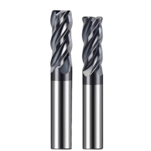
Cost-Reduction and Efficiency Strategies for Mold Shops: Quality Control in Overseas Bulk Procurement of Roughing End Mills
Procurement managers at North American and European mold shops frequently struggle to balance tool costs with delivery schedules. While traditional Western brands offer consistent quality, high unit prices severely pinch margins during heavy mold roughing. However, switching to overseas bulk purchasing without technical oversight often causes batch inconsistency and unpredictable tool life, increasing shop-floor downtime.
Our experience in building standardized tool supply chains shows that true cost reduction is not just buying cheap tools. It requires establishing quantifiable quality standards. When sourcing a wholesale rough endmill in bulk, shift your focus from unit price alone to overall Cost Per Part. Mastering tool consistency and tool life turns overseas procurement into a reliable profit booster for your shop.
How Engineers Evaluate Tool Consistency and Life When Sourcing Roughing End Mills in Bulk
A common mistake on the shop floor is evaluating an entire batch based on a single sample cutter. When receiving hundreds of tools, engineers must first spot-check outer diameter tolerance, tool runout, and microscopic edge quality. If runout varies by more than 0.005mm across the batch, one tool may cut perfectly while the next chips instantly under identical parameters, ruining automated workflows.
To build a reliable evaluation system, run tests using mold steel blocks with uniform hardness and a set benchmark (e.g., 500 cm³ material removal). Tracking spindle load curves and flank wear (VB values) reveals whether tool life follows a predictable normal distribution. Only a wholesale rough endmill with minimal batch-to-batch variation allows you to push parameters safely in automated production.
Lessons Learned: 3 Tool Details Often Overlooked by Western Workshops When Sourcing Chinese Roughing End Mills
Field feedback shows that roughing failures rarely stem from poor carbide substrates, but rather from overlooked micro-geometry details. First, examine flute polishing; residual grinding marks cause severe chip packing when machining hard steels. Second, check the corner radius transition. Serrated roughing cutters that lack a micro-chamfer on the tip will micro-chip the moment they hit the workpiece.
Third, never ignore shank tolerance and dynamic balance. When importing a china rough endmill, failing h6 shank tolerances or lacking G2.5 dynamic balancing causes minor centrifugal forces to amplify exponentially at high RPMs. Requiring suppliers to provide detailed inspection reports and microscopic flute geometry measurements before placing bulk orders effectively eliminates these hidden pitfalls.
Real-World Case Study: High-Quality Chinese Roughing End Mills Help a European Mold Shop Cut Per-Unit Roughing Costs by 35%
Last year, we optimized roughing operations for a mold manufacturer in Stuttgart, Germany, machining 718H automotive molds. They previously used expensive European brand cutters that drained project profitability. We supplied custom serrated carbide cutters with optimized flute geometry and coatings, then collaborated with their field engineers to recalibrate speeds and feeds.
In a month-long head-to-head production trial, this china rough endmill matched the European tool at over 90% service life while maintaining the exact same Metal Removal Rate (MRR)—at just one-third the unit cost. Factoring in tool wear, tool-change frequency, and labor, the shop cut its per-unit roughing cost by 35%. Partnering with industrial-grade overseas suppliers yields massive savings without compromising quality.

Troubleshooting Mold Roughing Operations and Maximizing Tool Life
Even top-tier cutters lose value if your team lacks rapid on-site troubleshooting skills. Mold roughing involves deep cavities, narrow slots, and skin scale, making chatter, heat accumulation, and abnormal wear everyday challenges. You must diagnose issues like a physician—analyzing sounds, chip morphology, and wear patterns to pinpoint root causes rather than blindly dropping parameters or swapping tools.
Maintaining process stability requires balancing tool condition with the cutting environment. Substrate selection, coating matching, and parameter tuning must adapt to real-world machine conditions. Establishing a systematic troubleshooting protocol maximizes the performance of your roughing endmill while keeping machine tool spindles completely safe.
Mitigating Chatter in Deep-Cavity Mold Machining: Parameter Adjustment Techniques for Roughing Endmills with High Overhang Ratios
System rigidity drops drastically when tool overhang exceeds 5x to 8x diameter in deep cavities, creating severe chatter. Machinists often react by drastically cutting feed rates, which causes the edge to rub instead of cut cleanly. If you face heavy deep-cavity chatter, break the resonance by dropping spindle RPM by 10–15% while keeping or slightly increasing feed per tooth to maintain adequate chip thickness for vibration dampening.
Additionally, using variable-helix cutters effectively suppresses chatter. The wave-edge geometry disrupts harmonic frequencies naturally. If your roughing endmill features a necked shank design, keeping radial width (Ae) within 10% cutter diameter while taking deep axial cuts (Ap) eliminates violent lateral vibration and regains stable cutting without sacrificing material removal rates.
Diagnosing Tool Wear Patterns: Determining When to Replace Roughing Endmills Based on Chip Shape and Flank Wear
Accurately timing tool changes protects parts and spindles during automated roughing. Relying on fixed timer intervals is unreliable; inspecting chip shape and flank wear provides clearer proof. Normal chips form uniform “C” shapes or tight coils with a light purple or golden tint. If chips turn into long ribbons or display heavy jagged burrs on the edges, your chip-breaker grooves have worn out.
For flank wear (VB), set 0.2mm to 0.3mm uniform wear as your safe tool-change threshold on 50+ HRC mold steel. If you spot micro-chipping on the flank face or thermal cracks extending toward the tool back, cutting zone temperatures have exceeded coating limits. Replacing the roughing endmill for steel promptly prevents catastrophic cutter breakage and avoids scrapping expensive mold components.
High-Pressure Coolant vs. Minimum Quantity Lubrication (MQL): Coolant Strategies to Extend the Life of Roughing Endmills for Steel
Choosing between wet and dry roughing depends heavily on material hardness and coating specifications. When machining pre-hardened steels (P20, 718H) below 40 HRC, high-pressure through-coolant (70+ bar) rapidly flushes chips and cools the cutting zone. However, on hardened tool steels above 50 HRC, low-pressure flood coolant causes thermal shock, triggering immediate thermal cracking in carbide substrates.
For dry machining hard mold steels, MQL or high-pressure air blast is far superior. Air blasts evacuate chips from deep cavities to prevent re-cutting, while minimal oil mist lubricates the rake face. If you are struggling with chip packing or selecting the right strategy for a roughing endmill for steel, feel free to share your drawings and material grades with us for custom field recommendations.






