


For many CNC pros, the most dreaded sound in the shop is that faint “click” coming from the spindle when running 304 or 316 stainless. That sound usually means one thing: the corner of your end mill just chipped.
Last month, we helped an aerospace client in California solve a frustrating 316L stainless steel project. They were using standard square-end mills and couldn’t get through three parts before the tool tips blew out. Dimensional accuracy was all over the place. The client asked us: “How do your carbide radius end mills run dozens of parts without a tool change?”
There’s no magic trick here. When you’re dealing with austenitic stainless steels—materials that are incredibly tough and prone to work-hardening—your success depends on how you use the geometry of a corner radius end mill. It’s the difference between a stable, lights-out operation and stopping the machine every hour to swap tools. We’ve found that many shops invest in high-end tooling but still use outdated “carbon steel” strategies for speeds, feeds, and chip management.
To help you avoid these pitfalls, we’ve put together six core insights from our real-world projects. These strategies aren’t just about making tools last longer; they’re about getting the full performance you paid for from your corner radius end mills suppliers.
When you’re up against an opponent as tough as stainless steel, are you sure your parameters are protecting that corner, or are you just accelerating its failure?
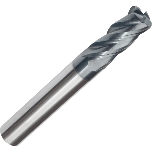
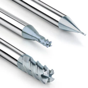
Why We Consistently Recommend Corner Radius End Mills Over Square End Mills for Stainless
Through our production monitoring, we’ve seen that 304 stainless is brutally sensitive to tool-tip stress. When you use a square-shoulder end mill with a deep axial cut, the cutting forces concentrate at one single, sharp point. Even with perfect parameters, those sharp corners often micro-chip because they can’t handle the cyclic stress and the work-hardening nature of the material.
That is why we always steer our clients toward a corner radius end mill. This isn’t about upselling; it’s about using a smooth structural transition. A radius distributes cutting forces across a curved arc rather than a single point. This design reduces chatter caused by radial force surges and prevents the tool’s most vulnerable section from being “devoured” by the material’s resistance.
Real-World Case Study: Solving Local Heat Buildup in 316 Stainless
Last autumn, we managed a high-volume project for 316 stainless valve bodies. The shop reported that their square-end mills were showing a purplish-blue discoloration at the tips—a classic sign of thermal failure. Because a sharp corner leaves almost no room for heat to escape, the temperature in that tiny zone spikes instantly. This caused the tool coating to oxidize and peel within minutes.
We stepped in and swapped the sharp tools for a version with a 0.5mm end mill corner radius for stainless steel. That tiny change completely shifted the thermal dynamics. The radius expanded the chip deformation zone, allowing heat to spread out instead of boring into the tool like a needle. The results were immediate: the “red-hot” glow vanished, and tool life doubled overnight.
Strength Comparison: How a Radius Handles 304 Stainless Resistance
From a physics standpoint, 304 stainless hits a cutting edge like a hammer. Our stress simulations show that square-corner tools have an incredibly high stress concentration at the very tip. This is why you’ll often see tool tips “rounded off” even when the rest of the flute looks fine.
The primary reason we use a carbide radius end mill is to optimize how that stress is shared. By using a curved arc for engagement, the force from the workpiece is redirected. A portion of that load is pushed back into the robust tool body rather than just the fragile edge. We don’t see this as a compromise; we see it as “machining artistry.” It gives the tool the resilience it needs to survive the intense reactive forces of stainless steel.

Optimal Selection Strategies for End Mill Corner Radiu in Stainless Steel
In our technical support calls, we often hear the same question: “When machining stainless steel, is a larger corner radius always better?” The answer is—not necessarily. It’s a constant balance between part geometry and tool rigidity. If you’re milling a mold cavity that requires sharp, square corners at the floor, a large radius will leave too much material. This creates a “heavy lifting” situation for your finishing tools. However, if the design allows it, adding even a 0.2mm radius provides an immediate boost to edge strength, especially on 316-series stainless.
We typically recommend choosing your end mill corner radius for stainless steel by working backward from the part’s smallest internal radius. Ideally, your tool radius should be slightly smaller than the drawing’s spec. This creates “dynamic clearance,” which prevents the tool from burying itself in the corners—a major cause of chatter. Remember, successful stainless machining isn’t about the fastest metal removal rate (MRR); it’s about maintaining thermal stability through smart geometry selection.
The “Golden Ratio”: How We Experimentally Determined Durable R-Values
While developing our carbide radius end mill series, we ran a battery of tests to find the “sweet spot” between axial depth of cut (Ap) and corner radius (Re). We found that if your axial depth is too shallow compared to the radius, the tool “rubs” or “scrapes” rather than cutting. This leads to instant work-hardening. Conversely, if you bury the tool past the radius, the peripheral edges take a beating. Our field-tested guideline is to keep your axial depth of cut between 2 to 3 times the corner radius.
This ratio keeps the cutting forces concentrated on the strongest part of the tool—the radius arc. When we see a customer’s tool corners wearing out prematurely, the fix is rarely a more expensive brand. Usually, it’s just a matter of fine-tuning the depth of cut or bumping up the radius size. This data-driven “tweak” is almost always the most cost-effective way to stabilize your process.
Why Large Corner Radii Yield Superior Finishes on 316 Stainless
From a micro-geometry perspective, scallop height is the enemy of a good finish. If you use a flat-bottomed mill on 316 stainless, even the tiniest amount of runout or a micro-chip on the edge will leave visible “tracks” on your part. A corner radius end mill acts like an “iron,” smoothing out the seams between passes where the paths overlap.
Furthermore, large radii improve chip morphology. Small radii tend to produce thin, needle-like chips that get dragged around and scratch the finished surface. Larger radii produce thicker, more “scroll-like” chips that evacuate cleanly. While a larger radius can increase radial forces, if your machine is rigid enough, it is the fastest way to achieve a mirror-like finish on tough alloys.
Practical Cooling and Lubrication Strategies for Carbide Radius End Mills
In our shop, we say that stainless steel machining is won or lost in how you manage heat. Stainless has terrible thermal conductivity, so the heat stays right at the cutting edge. If you don’t handle this, even the best carbide radius end mill will develop thermal cracks in under 30 minutes. We often see shops trying to get by with a single external coolant line, which is a recipe for disaster in thermal cycle management.
Effective tool life comes from “thermal equilibrium.” Instead of hunting for a “magic coating” after a tool fails, you need a scientific cooling strategy from the start. We look past just “coolant pressure.” We focus on whether the flow actually hits the interface where the radius meets the metal. For heavy cuts, we prioritize the “wetting” and penetration of the lubricant to reduce friction at the rake face. This stops heat before it even starts.
Say Goodbye to “Thermal Shock”: The Case for Internal Cooling
When roughing 304 or 316 stainless, our biggest enemy is “intermittent cooling.” If a tool is cutting at 800°C and gets hit by an uneven spray of coolant, it undergoes a “quenching effect.” This thermal shock causes micro-cracking and eventually leads to the corner falling off. This is why we always prioritize high-pressure internal cooling. If internal cooling isn’t an option, we find that powerful air-blast is often better than poor liquid cooling for keeping the tool temperature stable.
High-pressure internal cooling does more than just drop the temperature; it uses hydraulic force to blast chips out of the way. We’ve helped many corner radius end mills suppliers and shops realize that switching to internal coolant results in much more uniform wear. If you’re stuck with external lines, set up a “cooling curtain” using multiple nozzles to ensure the tool is never “dry” for even a fraction of a second.
Addressing “Stickiness”: Optimizing Chip Space
Stainless steel is notoriously “sticky,” and this buildup happens fastest right at the corner radius. Because the radius changes the direction of the chip, it can easily get trapped, leading to “re-cutting.” We once saw a deep-grooving job where the tools were snapping constantly. The culprit? Chips were “welded” into the flutes right at the radius. When the physical space is gone, the world’s best coating won’t save you.
To fix this, we advise either reducing the axial depth of cut or switching to a tool with fewer flutes to open up the “gullet.” In stainless, chip evacuation is sometimes more important than cutting speed. You have to give the chips an exit ramp. If you keep the chip flow smooth along the geometric contour of the radius, you prevent BUE and keep your workpiece from being scrapped.
Combating Work Hardening: Protecting Corner Radii by Adjusting Feed Rates
In our experience, work hardening is the ultimate “tool killer” in stainless steel. When you cut these alloys, the surface hardness spikes instantly, creating a “crust” that is much harder than the base material. If your next pass fails to penetrate this shell, your tool edge will just rub against it, generating massive friction. We always tell our peers: don’t “baby” the tool with light cuts. To protect a corner radius end mill, you have to decisively “cut into” the material to get beneath that hardened layer.
Adjusting your feed rate is really a search for the “sweet spot” between efficiency and tool life. Many operators instinctively slow down the feed to stay “safe,” but in stainless, that is a cardinal sin. A low feed per tooth causes the radius to slide and rub. This creates heat and pressure that destroys the tool’s geometry. We prefer a moderately high feed rate. By increasing the chip thickness, the heat stays in the chip and is carried away, keeping the carbide radius end mill chemically stable and sharp.
“Cut Through” vs “Grind Through”: Setting Minimum Feed Rates
When we optimize processes for 304 stainless, we emphasize one rule: “cut through” the metal, never “grind” it. If your feed per tooth (Fz) is smaller than the tool’s edge hone or the depth of the previous pass’s hardened layer, you aren’t cutting—you’re extruding. This causes rapid flank wear and can even snap the tool due to uneven stress.
In the shop, we set a “minimum safe feed” based on the tool diameter and R-value. For 316 stainless, we usually start at a minimum of 0.03 mm per tooth to ensure the edge bites into the soft base material. You’ll know you’ve hit the right mark when the cutting sound changes from a shrill shriek to a deep, steady hum. It feels counterintuitive, but an aggressive bite often leads to a much longer tool life.
The RPM Trap: Preventing Coating Failure and Annealing
Another common mistake we see is chasing high spindle speeds (RPM). Many believe high RPM equals high efficiency, but in stainless, excessive surface speed creates extreme heat right at the radius. Because the geometry of a corner radius end mill is complex, heat builds up fast. We’ve seen many tools where the side flutes are sharp, but the radius coating has turned grayish-white. That is a clear sign of annealing—the coating has literally cooked and lost its hardness.
Our strategy is “low RPM, heavy feed.” If your radius is wearing out too fast, try dropping your cutting speed by 20% while keeping your feed rate steady (or even bumping it up). This trade-off slashes frictional heat and prevents the cobalt binder from leaching out of the carbide. This simple move can boost your tool life by 30% or more. Keep that corner cool, and it will keep working for you.
Toolpath Optimization: Radius End Mills in Dynamic Milling
Dynamic milling (or trochoidal milling) has completely changed how we handle stainless steel. Traditional full-slotting is suicidal for a corner radius because the radial pressure is too high for that small curved profile. By using dynamic paths, we can use the full length of the flute while taking a small radial bite. This spreads the heat across the whole tool instead of burying it all in the radius.
We always prioritize a stable “Engagement Angle.” For 304 or 316 stainless, this optimization lets you push your spindle to its potential while protecting the radius cutter end mill from impact loads. You get a constant stream of thin chips, making tool wear predictable. In our experience, this “high-speed, low-load” approach is several times more efficient and much easier on your tool budget.
Using CAM Strategies to Avoid “Wrap-Around”
The most dangerous part of any contour is an internal corner. As the tool moves from a straight line into a corner, the engagement angle can jump from 30° to 180° instantly. This causes a massive spike in vibration and chips the edge. To protect your corner radius end mill, we always use “Trochoidal Entry” or “Arc Transitions” in our CAM software. This ensures the radius is never fully “wrapped” or engulfed by the material.
By fine-tuning the trochoidal radius, the tool stays in a tangential “peeling” state. We recently helped a client with a deep-cavity mold where the tool was “screaming” in every corner. By simply adding dynamic stock compensation, we killed the noise and saved the tool. A smart toolpath protects the tip better than the most expensive coolant.
Constant Load: Stopping the “Scream” in Deep Slots
Deep slotting is a nightmare, especially when your length-to-diameter ratio is over 4:1. Most people use a layered depth-of-cut, but that forces the radius to hit the work-hardened floor over and over. We prefer a dynamic slotting strategy with a constant load. This uses the strong radius as a pilot while the flutes advance in small, rapid increments. It keeps your spindle load meter at a steady, flat line.
When the load is constant, vibration drops significantly. This protects the radius from micro-impacts. If the machine is making a rhythmic “hissing” sound instead of a piercing screech, you’re in the green. It might make your program longer, but it doubles your tool life and leaves a much better finish.
Choosing the Right Corner Radius End Mill Suppliers
After years in this industry, we’ve seen buyers fall into “price traps” or “brand worship.” But the real test of a supplier is in the details you can’t see. When you’re cutting stainless, consistency is everything. Our first rule for choosing corner radius end mills suppliers is batch-to-batch consistency. If the first tool is great but the second one chips, the supplier lacks a standardized grinding and passivation process.
Second, look at their R&D. Stainless needs more than just a “hard tool”; it needs specific chip space and edge strength. Finally, ask about their carbide source. A high-quality substrate is the foundation of everything. If a supplier is vague about where their carbide comes from, you’re building your shop’s productivity on a foundation of sand.
Why Nanocoatings Matter
In the heat of a 316 stainless cut, coatings can delaminate. We look for specialized nanocoatings that act like “body armor,” blocking heat from reaching the carbide body. When we test tools, we look specifically at how the coating sticks to the radius curve. It’s easy to coat a flat surface, but complex radii are where cheap coatings fail and crack.
Top-tier suppliers also use “post-coating polishing.” If a coating is too rough, it increases friction and makes the stainless “stick” to the tool. We’ve found that polished nanocoatings can reduce friction by 30%. That’s a massive advantage for protecting your geometry and keeping the tool in the spindle longer.
Technical Support: Can They Solve Your Chatter?
A supplier should be your partner, not just a vendor. When your machine is screeching during a deep-cavity 316 job, you need someone who understands machine rigidity and tool-holder harmonics. We often help clients eliminate resonance by “dialing in” the overhang length or fine-tuning the RPM.
If your supplier’s only answer is “slow down the feed,” they don’t have the technical depth you need. Look for a partner who suggests variable helix designs or feed adjustments to shift the vibration frequency. A partner who will stand at the machine with you until the job is running right is the best guarantee for your bottom line.


