As an engineer with over fifteen years on the front lines of cutting tool manufacturing, the feedback I dread most isn’t about pricing. It is that late-night message from a client in North America or Europe: “We just started the run with your HRC65 ball end mill, and the tip chipped in less than thirty minutes.”
This scenario is common when machining ultra-high-hardness steels like S136 or ASP60. Last month, we helped a German client—a precision automotive mold maker—resolve this exact issue. Their machine rigidity was perfect and the tool coating looked flawless. Yet, their CNC ball nose end mill cutters suffered consistent micro-chipping during deep cavity rest-milling. The client suspected a brittle substrate. However, after analyzing their footage and parameters, we found the “culprit” hidden in subtle details often overlooked by the industry.
In our experience, the core challenge of ball end mill hardened steel applications isn’t just the hardness. It is the management of cutting force fluctuations and thermal stress. As a specialized ball end mill cutter manufacturer, we know that at HRC65, the compressive stress on the cutting edge is several times higher than in standard milling. If your toolpath ignores the fact that the center of a ball nose has zero cutting speed, or if your cooling strategy is wrong, even the best tool will fail.
Chipping isn’t random. It is the consequence of an imbalance between rigidity, TIR (runout), and geometry. Let’s stop talking about theory and dissect what is actually robbing your tools of their service life.
You’ve verified your speeds and feeds. So why did that “hard steel” cutter still fail at the first critical corner?
Three Core Reasons for Premature Failure in Hard Steel Machining
After years of technical support for Western machine shops, we’ve found that premature wear rarely stems from material defects. Instead, it happens when the physical boundaries of the machining environment are violated. In our lab, we’ve seen how “fragile” these tools become when we push HRC65 steel. That fragility is the trade-off for the extreme hardness required to cut treated steel. Machining at this level is like dancing on a tightrope; any minor resonance or thermal imbalance can destroy a tool in seconds.
Our analysis of thousands of field failures shows that 80% of issues stem from three factors: overhang rigidity, thermal shock from cooling, and the geometric “dead zone” of the ball nose. It is rarely a simple “break”; it is a failure to reach equilibrium. The following insights are hard-won lessons from real-world scrapped workpieces.
Deflection (Chatter): The Invisible Killer of Long-Reach Tools
For deep cavities, shops often rely on long-neck cnc ball nose end mill cutters. Our data shows that when the L/D ratio (overhang length to diameter) exceeds 5x, micro-vibrations—or chatter—increase exponentially. In one European project, we increased a tool’s overhang from 30mm to 45mm while cutting HRC65. The impact force on the tool tip radius jumped by 120%. This high-frequency oscillation, though invisible, induces fatigue spalling on the carbide edge almost instantly.
For deep-cavity work, we always recommend tapered-neck designs over uniform-diameter shafts. The tapered structure significantly boosts static rigidity. If you must use a long overhang, keep your radial depth of cut (Ae) between 1% and 2% of the tool diameter. We would rather see you take more passes than snap a tool due to radial runout. In hardened steel, rigidity is your only lifeline.
Thermal Shock: Why Traditional Coolants Kill Hardened Steel Cutters
This is a misconception we correct weekly. Many operators blast high-pressure coolant to fight the heat of ball end mill hardened steel processing. However, at HRC65, the cutting zone temperature often exceeds 800°C. Intermittent “icy” coolant creates an extreme thermal gradient. This causes micro-cracks in the carbide. What looks like “chipping” is often a thermal crack that propagated into a brittle fracture under mechanical load.
At our testing centers, we’ve proven that MQL or a simple high-pressure air blast is superior. Air blasting evacuates hot chips to prevent “re-cutting” while maintaining a stable edge temperature. We advise our clients to kill the water pumps and stick to dry machining. This allows the tool coating to act as a heat shield rather than delaminating from constant thermal cycling.
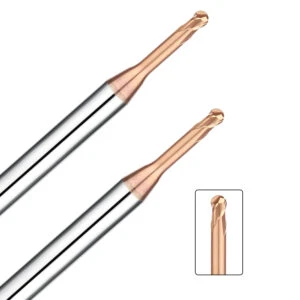
The Zero-Velocity Pitfall: Rethinking Entry Strategies
From an engineering standpoint, the center of a ball end mill cutter is a physical trap. Because the cutting speed (Vc) at the dead center is theoretically zero, the tool doesn’t “cut” there—it “extrudes” the material under immense pressure. We often see tools fail because they were plunged vertically into HRC65. The tip cannot generate a chip, the thrust force spikes, and the center of the ball nose collapses.
To fix this, we guide clients toward ramping paths or helical entries. Keep your entry angle between 1° and 3°. This shifts the initial contact to the side of the radius where the linear velocity is high enough to form a healthy chip. It adds a few seconds to your cycle time, but it ensures the tool starts in a “cutting” state rather than a violent extrusion.
How We Reduce Chipping Risk Through Optimized Tool Geometry
As a specialized ball end mill cutter manufacturer, we know there is a massive gap between a clean laboratory test and the reality of a shop floor cutting HRC65 steel. When material hardness spikes, standard tool designs hit a physical wall. Most chipping isn’t caused by bad parameters; it happens because the tool’s geometry wasn’t built for that specific stress level. In our design process, we prioritize edge stability over raw cutting speed, finding the “sweet spot” between sharpness and structural integrity.
In our R&D workflow, we simulate the force vectors acting on the tool tip the moment it hits the workpiece. By fine-tuning the helix angle, core diameter ratio, and micro-geometry, we eliminate stress concentrations. We aren’t just making the tool “thicker”—we are reshaping the cutting edge at a nanoscale level. Here are the two core design principles we use to help our clients in North America and Europe multiply their tool life without losing precision.
Negative Rake Angle: Strengthening the Edge for HRC65 Hardened Steel
Traditional theory says a larger rake angle means a sharper tool. That logic fails when machining HRC65 steel. While a positive rake angle feels “light” and smooth, its thin edge is prone to brittle fracture under heavy loads. By adopting a negative rake angle, we transform the cutting forces from outward shearing forces into inward compressive forces. This leverages the natural compressive strength of carbide, protecting the most vulnerable part of the cnc ball nose end mill cutter—the edge—from snapping.
Real-world testing shows that while a negative rake angle slightly increases spindle load, the gain in reliability is massive. This design is a lifesaver during interrupted cuts or when hitting hard oxide scale. We typically tune these angles between -5° and -15° based on your specific material. For B2B production where stability is king, sacrificing a bit of “lightness” for an unattended, full-shift run is the smarter professional choice.
Edge Honing: Why We “Dull” Every Ball End Mill Before It Leaves the Factory
Newcomers often ask: “If I’m buying a premium tool, why is the edge rounded?” In reality, this is a critical step for any high-end ball end mill cutter. Under a microscope, a freshly ground edge has tiny, invisible serrations (nicks). In HRC65 steel, these nicks act as stress risers that lead to instant chipping. Through micron-level edge honing, we transform that sharp, jagged line into a smooth, reinforced arc radius.
This secondary rounding allows cutting forces to enter the material gradually, drastically reducing micro-chipping during the “break-in” phase. Our tests show that honed tools exhibit a 40% lower wear rate than untreated ones. Although it increases our manufacturing costs, we consider precision honing a non-negotiable baseline for quality. It ensures you get stable performance from the very first cut.
On-Site Strategies for High-Efficiency Hardened Steel Machining
Our global technical support experience shows that Western B2B clients rarely lack quality tools; they lack standardized application protocols. Machining ball end mill hardened steel isn’t about cranking up parameters—it is about the strategic harmony between system rigidity and toolpath logic. We’ve seen $500,000 5-axis centers fail because of a poor clamping choice or an outdated toolpath. This waste is 100% avoidable.
To help our clients standardize, we’ve built a workflow focused on “eliminating variables.” From controlling TIR (Total Indicated Runout) to optimizing CAM algorithms, every step must protect the edge. We don’t believe in “magic” tools; we believe in systematic optimization that results in a quiet, constant, and efficient process.
Rigidity Matching: Why Shrink-Fit Holders Beat Collet Chucks for HRC65
In our shop diagnostics, runout is the #1 killer of ball nose mills in hard steel. At HRC65, a deviation of just 0.01mm can overload a single flute by 200%. Unlike complex collet chucks, we strongly recommend shrink-fit holders for finishing. Their monolithic, symmetrical design provides massive centripetal force and keeps TIR within 0.003mm. This is the only way to ensure stability during micron-level feeds.
Beyond accuracy, the slim profile of shrink-fit holders offers better clearance for deep cavities, reducing the need for long tool overhangs. We’ve seen many shops struggle with inexplicable resonance using side-lock holders, only to have the vibration vanish the moment they switched to a shrink-fit system. The initial investment is higher, but it is much cheaper than scrapping $300 tools and wasting expensive machine hours.
Trochoidal Milling: Using Algorithms to Protect Your Ball End Mill
As engineers, we believe in “using the algorithm to save the tool.” The cardinal sin of hard machining is plunging a tool into a sharp 90-degree corner. The sudden spike in the engagement angle is a nightmare for a cnc ball nose end mill cutter. We recommend all clients move to trochoidal milling or high-efficiency dynamic paths. These strategies use circular motions to keep the tool’s arc of contact constant, ensuring stable temperatures and predictable load.
This fundamentally changes the stress on the tool. Because the load is constant, you can actually increase your speeds and feeds without fearing a chip at every corner. We recently optimized a project for a U.S. medical device manufacturer—after switching to a constant-load path, efficiency jumped by 30% and tool life doubled. In the world of hard machining, stability trumps speed, because stability is what allows you to finish the job without a tool change.
Why Choosing a Ball Nose End Mill Manufacturer with Real-World Experience Is Crucial
In CNC machining, blueprint parameters are just a starting point. Real success depends on “engineering intuition”—something you won’t find in a manual. As a ball end mill cutter manufacturer, our day isn’t spent just tweaking CAD models. We spend it analyzing wear patterns under the roar of high-speed spindles. For B2B clients cutting HRC65 steel, you don’t just need a box of tools; you need a partner who can translate your machine’s acoustics and surface textures into actionable data.
Practical experience means we have lived through your nightmares—from micro-chipping to deep-cavity chatter. We’ve built those lessons into our tools, from the micron-level edge passivation to the tungsten carbide grain size. We believe that only by understanding the harsh reality of the shop floor can we engineer tools that give operators genuine confidence.
From Lab to Spindle: Refining Tools Through Extreme HRC65 Testing
At our facility, we have a rule: before any HRC65 ball end mill reaches a customer, it must survive 50 hours of continuous, extreme-load cutting. We deliberately simulate the worst conditions, such as cutting hardened mold steel with irregular stock allowances and unstable fixturing. This “trial-by-fire” R&D lets us observe microscopic performance at every stage of potential failure, allowing us to reverse-engineer a more stable tool.
If you are working with high-hardness materials and strict finish requirements, look at your tool discard rates. If failures are random or inconsistent across different toolpaths, your current tool’s design redundancy is likely too low for real-world variables. Our goal is to minimize these variables so that our tools perform as stably on your spindle as they do in our lab.
Solving Problems, Not Just Selling Tools: Support for the West
Years of dialogue with engineers in North America and Europe have taught us that the best support is a case-by-case approach. We don’t push the most expensive tools; we find the optimal balance for your specific application. Whether we are optimizing an entry path for a cnc ball nose end mill cutter or fine-tuning a coating for a niche material, we act as a remote extension of your process.
If you are struggling with a complex deep-cavity structure or switching to harder materials to extend mold life, let’s talk. You can send us your machining parameters, machine models, or a simple diagram of your setup. We can determine together if you need to adjust your ramping angle to avoid the “dead zone” or switch to a more rigid clamping system to kill vibration. Technical exchange between engineers will always provide more value than a sales quote.
白底-主图2.webp)