In CNC machining, the geometry of the end mill directly influences cutting performance, machining quality, and tool life. Selecting the right end mill geometry not only improves machining efficiency but also extends tool life and reduces manufacturing costs.
This article systematically analyzes three key geometric elements of end mills — flutes, helix angles, and end types — to help engineers better understand the features and benefits of various end mill designs in practical applications.
By examining how these geometric parameters correspond to workpiece materials and cutting methods, this guide provides practical, forward-looking insights for tool selection. Whether you’re working in precision mold manufacturing or machining aerospace and automotive parts, understanding the design logic behind end mill geometry is essential for enhancing machining stability and surface finish.
If you seek solutions for efficient chip evacuation, high-temperature cutting, or precision surface machining, this article offers detailed technical guidance. It will clarify the suitability of different flute designs for aluminum alloys, steels, and composite materials, explain the impact of helix angle on cutting forces and surface quality, and provide deep insights into the performance of various tool tip structures under real working conditions.
Why End Mill Geometry Matters
In modern CNC machining, the endmill is more than just a cutting tool — its geometry fundamentally determines overall tool performance, including cutting efficiency, surface finish, tool life, and process stability. For any engineer focused on precision manufacturing, mold making, or batch production, mastering end mill geometry is key to achieving high-quality results.
Determining Factors for Processing Efficiency and Surface Quality
The geometry — comprising flutes, helix angle, and end type — is the core factor influencing material removal rates and surface roughness.
For instance, high helix angles reduce cutting resistance and enhance chip evacuation in high-speed machining, which lowers surface scratches and improves finish. Conversely, multi-flute end mills may increase processing speed per pass but can suffer from chip congestion, reducing surface quality.
Optimizing end mill geometry is especially critical when working with tough materials like mold steels and titanium alloys, balancing efficiency and quality.
Key Structures Affecting Tool Life and Process Stability
Well-designed end mill geometry improves rigidity and vibration resistance, extending tool life and ensuring stable cutting. In hard or interrupted cuts, appropriate tool tip geometry minimizes local stress, delaying wear and chipping.
Core thickness, flute width, and chamfering affect thermal stability and vibration damping during machining. High-performance end mills rely on sound geometric design to maintain process stability and durability, especially in long or dry cutting operations.
Selecting the right geometry for specific machining conditions—whether high-speed, dry, or complex 3D milling—is essential for tool longevity and process consistency.
Overview of Key End Mill Geometry Features
End mill geometry defines its suitability for various machining tasks. A deep understanding of flutes, helix angles, and end types helps CNC engineers select tools that match material, feed rates, and process goals. The following sections analyze each feature and its practical applications.
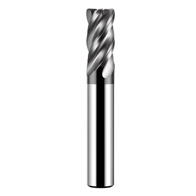
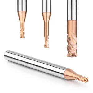
Flutes
Flute count is crucial for chip removal and tool strength. Common designs feature 2, 3, 4, or more flutes:
-
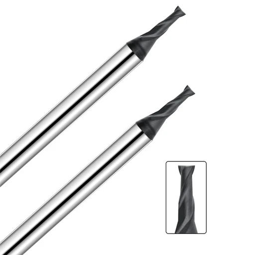
2 or 3 flutes: Best for soft materials like aluminum, providing larger chip space and reducing clogging.
-
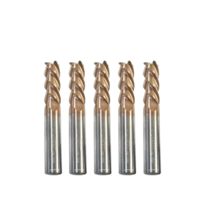
4 or more flutes: Better rigidity and stability for hard materials like steel, but reduced chip clearance.
Choosing the correct flute count based on machining conditions is fundamental to optimizing cutting performance.
Helix Angle
Helix angle influences cutting stability and surface finish:
-
30°: Standard angle, balancing stability and tool life.
-
45°: High helix, smoother cutting and better finishes, ideal for stainless steel and soft metals.
-
60°: Very high helix, maximizes chip removal and finish in aluminum but requires strong tools.
Selecting helix angle depends on material type, cutting speed, and desired surface quality.
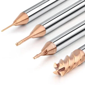
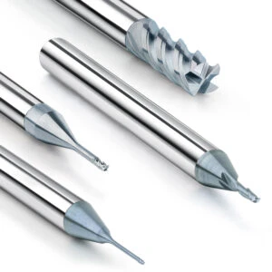
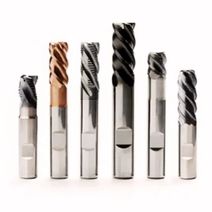
End Types
Tool tip geometry affects cutting method, accuracy, and application:
-
Flat End Mill: For general milling, roughing, and finishing of hard materials.
-
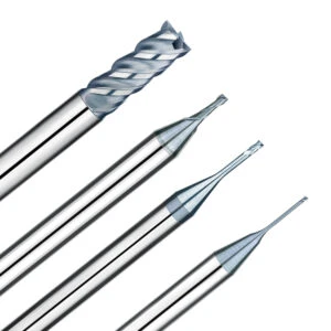
Ball Nose End Mill: For 3D contouring, molds, and complex surfaces.
-
Corner Radius End Mill: Adds strength and anti-chipping, ideal for transition fillets.
For example, when machining 3D surfaces or mold cavities, ballnose milling cutters should be preferred to obtain smoother surface contours. When performing slotting or chamfering operations, the cutting characteristics and rigidity of the tool tip need to be considered.
Reasonable selection of tool tip structure can not only improve the stability of the cutting path, but also extend the tool life and reduce processing errors. Therefore, how to choose the appropriate end mill tool tip form under different working conditions is an important part of improving overall manufacturing efficiency and precision control capabilities.
Matching Geometry with CNC Applications
The cutting characteristics, surface quality requirements and cooling conditions of different materials determine the selection strategy of the end mill geometry. Reasonable matching of geometric parameters can not only improve machining efficiency, but also significantly extend tool life, improve part consistency and yield rate.
High-Speed Dry Cutting and Hard Materials
In high-speed dry cutting or hard material processing (such as steel parts above HRC 50, titanium alloy, heat-resistant alloy), the tool needs to withstand high temperature, high impact load and continuous processing challenges. At this time, the geometric parameters and surface coating selection of the end mill are particularly critical.
It is recommended to use an end mill with 4 or more flutes to enhance the rigidity and vibration resistance of the tool. In a non-coolant environment, the more flutes there are, the more stable the cutting path can be.
Tool coatings (such as AlTiN, TiSiN or CVD diamond) should be used in conjunction with the flute design to effectively insulate and reduce tool wear.
In terms of helix angle, a medium-low helix angle end mill of 30° or less should be selected to control the conduction of cutting heat to the workpiece and improve overall thermal stability.
Therefore, when selecting the geometry of an end mill for high-speed dry cutting, special attention should be paid to the dynamic balance between “number of flutes-rigidity-helix angle-coating” to achieve optimal cutting performance.
Aluminum and Non-Ferrous Metals
Aluminum alloy and non-ferrous metals such as copper and brass have strong ductility and thermal adhesion. “Tool sticking” is very likely to occur during processing, affecting surface quality and accelerating tool wear. At this time, the geometry of the end mill needs to focus on optimizing chip removal and anti-sticking performance.
It is recommended to use an end mill with 2 or 3 edges and a wide groove spacing to maximize chip removal space and avoid the formation of built-up edge.
In terms of helix angle, a medium-high helix angle of 30°~45° is more suitable to improve chip removal smoothness and reduce cutting vibration.
The cutting edge should be sharp to avoid negative rake angles. Mirror polished groove surfaces or uncoated tools can be selected to reduce the risk of adhesion.
In addition, many manufacturers will develop special aluminum end mill geometries for this type of material, with special cutting edge rake angles and improved groove designs. Therefore, in the geometric design of aluminum alloy milling to avoid tool sticking, the strategy of balancing chip removal efficiency and blade sharpness should be given priority.
Finishing and Mirror Surfaces
For the finishing of molds, optical parts or high-precision mechanical parts, especially for scenes requiring submicron surface roughness (Ra < 0.2μm) or mirror effects, the geometry of the end mill must have extremely high stability and finish control capabilities.
It is recommended to use a low-vibration end mill with a multi-edge (more than 4 edges) design to refine the cutting thickness, reduce burr formation and improve surface integrity.
In terms of helix angle, 35°~45° can provide good cutting smoothness and medium chip removal ability, which is suitable for fine processing under slow tooling.
Corner radius or ball nose end mills can avoid sharp corner chipping, especially suitable for processing fine parts such as transition surfaces and mold radii.
In addition, in the finishing of hard materials, diamond-plated or super-hard coated end mills can be selected to extend tool life and achieve high mirror accuracy. These tools have become the preferred solution for the mold processing industry in terms of geometric optimization of finishing and mirror-level milling.
Common Mistakes in Choosing End Mill Geometry
Despite advanced CNC tech, many engineers misunderstand geometric parameters, causing efficiency loss, tool wear, and scrap.
“More Flutes, Better Performance” Misconception
Many beginners often mistakenly believe that the more blades, the better the machining effect when choosing end mills. In fact, although multi-blade end mills (4-blade, 6-blade or even 8-blade) have higher contact cutting points and potential surface quality advantages, they are not suitable for all working conditions.
In rough machining or soft metal machining, such as aluminum alloy, copper and other materials, it is more advantageous to use 2-blade or 3-blade end mills. Because the slot spacing is larger, the chip removal space is more sufficient, and the cutting is smoother.
Multi-edge end mills will cause a larger contact area and cutting resistance during processing, which can easily lead to tool overheating and workpiece built-up edge problems, especially in a non-coolant environment.
Therefore, the understanding of the “scope of application of multi-edge end mills” should be based on the processing material, cutting depth and chip removal requirements, avoiding blindly pursuing the number of edges and ignoring the actual performance.
Overlooking Helix Angle Effects on Cutting Direction
Another often overlooked issue is the relationship between helix angle and cutting direction. The helix angle of the end mill not only affects the weight of cutting, but also directly determines the direction of cutting force and workpiece stability.
Although a high helix angle (such as more than 45°) can bring smoother cutting and better surface quality. But it will also generate a large upward force, which is easy to cause the workpiece to tilt or vibrate when the clamping is not firm.
On the contrary, a low helix angle (such as 30°) is more stable, but the chip removal ability and processing finish are relatively reduced.
Especially in side milling, cavity processing or cantilever workpiece processing, the wrong helix angle selection will cause serious problems such as positioning instability and tool runout. Therefore, correctly understanding the “influence of helix angle on milling direction” is of decisive significance for ensuring processing accuracy.
Ignoring Tool Tip Geometry and Material Matching
End types are a very critical but often overlooked part of end mill geometry. Different tool tip geometries have obvious differences in adaptability to workpiece materials and processing forms.
When processing hard materials such as steel and titanium alloys, sharp-angle flat-end cutters are often more prone to chipping. Tools with rounded corner transitions or chamfer designs should be selected to improve tool tip strength and impact buffering capabilities.
When processing 3D surfaces, mold curves or free-form surfaces, the ball-end end mill geometry can achieve smoother transitions and detailed depictions to avoid tool mark accumulation.
If an inappropriate tool tip type is used when chamfering or grooving, not only will the design requirements not be met, but the edge of the workpiece may even be damaged.

How to Choose the Right End Mill Geometry
Selecting the correct end mill geometry is critical for improving machining efficiency, extending tool life, and ensuring part accuracy. Different machine tool rigidity, material types, and machining methods require specific end mill geometries. Therefore, relying solely on experience or generic “all-purpose” tools is insufficient—selection strategies must be tailored to actual operating conditions.
Whether you’re seeking the best end mill geometry for aluminum, or the ideal tool design for hard materials or high-speed dry cutting, the following factors form the foundation of an informed decision.
Formulate a Plan Based on Machine Tool Speed, Material Type, and Cutting Method
Machine Tool Spindle Speed and Rigidity
High-speed spindles (above 15,000 rpm) perform best with end mills featuring high helix angles and light cutting designs. These geometries help reduce vibration and cutting resistance during high-speed operations.
Conversely, low-speed, heavy-duty machines benefit from tools with robust cutting edges and low to medium helix angles to enhance edge strength and resist chipping.
Workpiece Material Properties
-
Non-ferrous metals like aluminum alloys and brass: Use 2-flute or 3-flute end mills with low helix angles to facilitate chip evacuation and reduce tool sticking. For high-speed aluminum milling, end mills with polished flute walls are often recommended to improve chip flow.
-
Medium to high-strength materials, such as steel and stainless steel: Opt for 4-flute or multi-flute end mills with suitable coatings and carefully designed rake angles to balance tool strength and chip removal.
-
Hard and brittle materials, including titanium carbide and glass fiber composites: Prefer PCD (polycrystalline diamond) or CVD diamond-coated tools with rounded corners or ball-nose geometries to minimize stress concentration on the tool tip.
Cutting Method and Tool Path Strategy
-
Side milling and cavity machining: Flat end mills with medium helix angles (typically 30° to 45°) are recommended to improve depth control and maintain stable multi-axis toolpaths.
-
Profiling and 3D surface machining: Ball nose or corner radius end mills provide better surface finishes and smoother contour transitions.
-
Chamfering and plunging: Specially designed end mills with chamfered or double-angle cutting edges enhance entry and exit stability during plunge cuts.
H3:Recommended Application Scenarios and Typical Tool Type Combinations
| Machining Type | Material Type | Recommended End Mill Geometry |
|---|---|---|
| High-Speed Aluminum Machining | Aluminum, Copper, Plastics | 2-flute/3-flute, low helix angle, polished flute walls |
| Mold Cavity Finishing | Pre-hardened Steel, Carbon Steel | 4-flute, corner radius, medium helix angle |
| Hard Material Dry Cutting | Titanium Carbide, Fiberglass | PCD or CVD coated, multi-flute, high helix angle |
| Flat Surface Finishing | Stainless Steel, Alloy Steel | 4 to 6 flutes, low-vibration design, blunt rake angle |
| Profiling & 3D Surface Milling | Various Metals and Resins | Ball nose, double-flute ball nose, micro-edge design |

Correctly Understanding End Mill Geometry to Improve Machining Quality and Tool Life
Choosing the right end mill geometry is fundamental for achieving efficient machining and superior surface quality. This article’s detailed breakdown of key geometric factors—flute count, helix angle, and tool tip design—combined with application-specific matching strategies, underscores several essential points:
-
Flute design impacts not only chip evacuation but also machining efficiency and cutting stability.
-
Helix angle selection influences cutting force distribution and surface finish quality. Higher helix angles favor high-speed machining, while lower angles excel in heavy cutting.
-
Tool tip geometry must align with workpiece shapes and machining needs to ensure precision and optimal results.
Equally important is avoiding common selection mistakes, such as blindly opting for more flutes, neglecting helix angle effects, or mismatching tool tip design with material properties. These errors can compromise machining outcomes and reduce tool longevity.
For CNC engineers and tool buyers, a scientific approach to selecting end mill geometry—based on machine performance, workpiece material, and cutting strategy—is essential. Employing a comprehensive selection strategy that integrates end mill types and end mill cutter selection optimizes tool performance, boosts processing quality, and enhances production efficiency.
In conclusion, a thorough understanding and proper application of end mill geometry can significantly reduce manufacturing costs and extend tool life, representing a key step toward efficient, high-precision machining.