


When working with high-hardness metals—specifically those exceeding HRC 50—many machinists hit a wall. The parameters and cutting tools that performed flawlessly on standard P-class steels suddenly yield an abysmal surface finish the moment they encounter hardened steel.
Just last month, we assisted a Boston-based client specializing in precision automotive molds. They were machining a batch of heat-treated mold steel (HRC 50–52) using standard carbide milling cutters. The workpiece surfaces consistently exhibited visible chatter marks and irregular microscopic tearing (galling). To meet the required Ra 0.8 finish, they were forced to drop the feed rate to a glacial crawl, causing their lead times to spiral out of control.
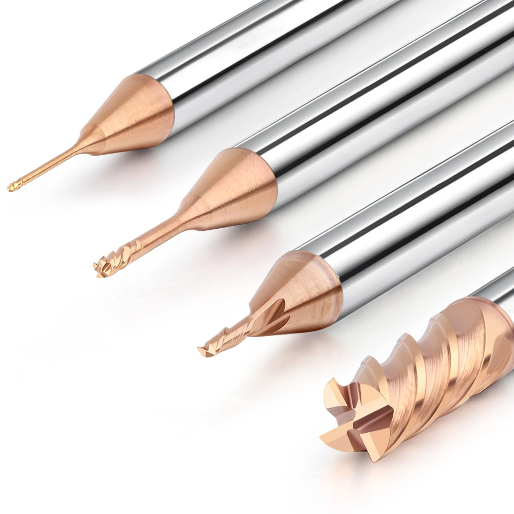
This is a “stubborn problem” we, as carbide end mill cutter manufacturers, have addressed repeatedly over the past 15 years. Many assume that simply buying a tool labeled “milling cutter metal HRC 50” is enough. But based on our hard-won experience on the shop floor, surface quality issues often stem from overlooked micro-geometry and dynamic cutting rigidity.
To resolve the Boston case, we didn’t just look at lab data. We swapped in our higher-tier HRC 65 end mill bits to conduct “down-rated” finishing tests. We discovered that the issue often isn’t a defective tool. Instead, it’s a lack of understanding regarding the amplifying effects that edge honing and radial runout have in high-hardness environments.
Have you ever felt that frustration? Watching the spindle spin at blistering speeds, only to see a surface that looks like it was gnawed on by a dog?
BUEand Annealing: Why High-Quality Carbide Milling Cutters “Go on Strike” at HRC 50
In our workshop, we see this constantly: a brand-new, high-end carbide milling cutter sounds crisp for the first ten minutes, then the finish takes a nosedive. Most peers blame the tool quality. However, our diagnostics show the real culprit is the extreme thermal load generated at HRC 50. When localized heat exceeds the tolerance of the substrate or coating, softened chips instantly weld to the cutting edge—creating a BUE.
The danger of BUE is its instability. It constantly forms and detaches, tearing away microscopic fragments of the carbide substrate each time it breaks off. Even a meticulously designed tool will suffer rapid thermoplastic deformation if the balance between heat and chip evacuation is lost. This transition—from “cutting” to “plowing”—destroys the surface finish and causes the workpiece to fall out of dimensional tolerance.
Don’t Be Misled by Cutting Speeds: The Critical Temperature Thresholds for HRC 50 Metals
During laboratory testing of milling cutter metal HRC 50 series, we uncovered a fascinating phenomenon. Many engineers consult standard charts and assume higher cutting speeds (Vc) always mean higher efficiency. But at HRC 50+, even a marginal increase in Vc can trigger an exponential temperature spike. Once the cutting zone breaches 800°C, the material undergoes secondary hardening or annealing. This cyclical change in physical properties is the primary cause of surface chatter.
If your finish is unstable, try reducing the Vc by 10–15%. Watch the chips. If they shift from deep purple back to a pale blue, you’ve likely found the first step toward restoring surface quality. Effective thermal management is a balancing act with your feed per tooth (fz). An excessively low feed rate causes the edge to rub rather than cut, generating more frictional heat. We guide our clients to find that “sweet spot” where the chips carry away the heat. In high-hardness machining, heat is the enemy, but speed is a necessary evil for chip formation.
The Truth About Coating Delamination: How Coating Adhesion Impacts Surface Finish
As a China carbide milling cutter manufacturer with a long history of exporting to the US and Europe, we know how much coating delamination hurts B2B clients. Often, a bad finish isn’t caused by wear, but by the coating peeling away. This leaves the bare carbide to clash directly against the HRC 50+ hardened layer. We’ve found that slight deviations in pre-coating sandblasting or PVD furnace vacuum control cause the coating to flake off like fish scales under stress.
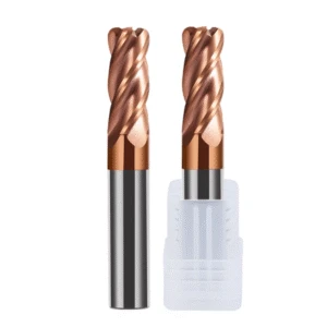
When helping Western clients with tool life stability, we prioritize adhesion testing for PVD coatings. If you see a “whitening” effect on the edge in under 30 minutes, the coating process was likely substandard. For demanding finishing, we recommend upgrading to HRC 65 end mill bits. These coatings typically feature higher aluminum or silicon content to withstand thermal fatigue. Ultimately, a superior finish depends on edge durability—your coating is the “body armor” that determines survival.

Troubleshooting Chatter: The Art of Balancing Rigidity When Using HRC65 End Mill Bits in Deep Cavities
In deep-cavity mold machining, chatter is a nightmare—especially when using HRC65 end mill bits on high-hardness materials. During a project for an automotive body panel mold destined for Germany, we noticed a recurring issue. Once the tool’s length-to-diameter ratio exceeded 4:1, the resonance generated upon contact with the HRC 50+ metal left dense striations on the workpiece walls. This chatter doesn’t just ruin the finish; the alternating stresses quickly cause micro-chipping on brittle carbide tips.
We often tell clients that resolving deep-cavity rigidity isn’t just about “slowing down.” Blindly reducing spindle speed can push the system into a low-frequency vibration zone, making the problem worse. Instead, we analyze system rigidity. This includes verifying the clamping system’s pull-down force and ensuring proper inertia compensation during high-speed directional changes. In high-hardness machining, rigidity is a state of balance—it’s about dissipating excess energy while maintaining cutting efficiency.
Overhang Length and Vibration Amplitude: How We Suppress Resonance with Variable Helix Designs
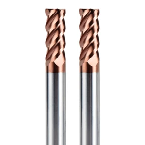
For long-overhang applications, traditional symmetrical cutting edges often act as catalysts for resonance. When every edge strikes the material at the same frequency, vibration amplitudes spiral out of control. To disrupt this, we incorporate variable helix angles and variable cutting edge angles into our premium carbide end mills. This ensures that the timing and direction of cutting forces vary from one edge to the next, killing resonance at its source.
The performance shift on HRC 50+ materials is tangible. We once advised a client performing deep-cavity root clearing to switch from standard tools to this asymmetrical geometry. With the same overhang, the cutting sound transformed from a piercing shriek into a steady, low-frequency hum. Structural optimization at the tool level is far more effective than tweaking RPM or axial depth of cut (Ap). While the grinding costs for these tools are higher, the investment is clear when compared to the cost of scrapping an expensive, hardened workpiece.
Toolholder Runout is the Enemy: Why We Limit Runout to 0.005mm for HRC65-Grade Tools
Many machinists buy expensive carbide milling cutters only to mount them in old, generic toolholders. This is wasteful. In high-hardness machining, if tool tip runout exceeds 0.01mm, the process becomes unbalanced. Effectively, only one or two edges bear the entire load, while the others generate violent impacts. This causes periodic surface defects and can slash tool life by over 50%.
Our technical requirement is strict: for finishing with HRC65-grade tools, dynamic runout at the spindle nose must stay within 0.005mm. We strongly recommend shrink-fit holders or high-precision hydraulic chucks over standard ER collets. After 16 years in the field, we’ve validated one fact: if the runout isn’t resolved, achieving a mirror finish on HRC 50+ metal is purely a matter of luck.
Optimizing Feed Marks: As Carbide End Mill Cutter Manufacturers, How Do We Adjust Geometry?
Feed marks are a major technical barrier to the ultimate surface finish. As carbide end mill cutter manufacturers, we’ve found that high-hardness machining has zero tolerance for surface imperfections. On HRC 50 workpieces, the microscopic peaks and valleys left by the feed per revolution are sharp and intractable. Simply reducing the feed rate often backfires, leading to cutting force fluctuations and thermal fatigue at the tool tip.
We prefer to “eliminate” these marks by optimizing the tool’s micro-geometry. During R&D, we adjust the curvature of the side edges and the gradient of the relief angles to alter how the edge interacts with the surface. We aren’t just making a tool; we are designing a cutting trajectory. If a surface looks bright but feels “tacky,” there is geometric interference. Even a micron-level adjustment can determine whether a part needs costly manual secondary grinding.
Calculating Residual Area Height: Why We Fine-Tune R-Angle Compensation for HRC50 Materials
Theoretical “Cusp Height” formulas often fail in the real world of HRC 50 machining. When manufacturing our milling cutter metal HRC 50 series, we apply asymmetrical compensation to the ball nose or corner radius. This is necessary because hardened materials have a much stronger “spring-back” (elastic recovery) effect than softer metals. A perfectly circular R-angle would actually produce minute wave-like undulations due to uneven material resistance.
On-site, we use actual roughness data to reverse-engineer the required compensation for the edge geometry. This fine-tuning ensures depth stability even when machining blocks with non-uniform hardness. Achieving precise “pre-compensation” requires an extensive cutting database. This strategy—incorporating material resistance into the design—is how we help clients break through Ra value bottlenecks.
Climb Milling vs. Conventional Milling: Field Insights for High-Hardness Materials
For finishing high-hardness materials, we have conducted exhaustive internal tests. Reports on our China carbide milling cutter series show that while Climb Milling typically offers a better finish, it carries risks at HRC 50+. The impact load at tool entry can easily chip a delicate finishing edge. Furthermore, if the machine’s lead screw has any backlash, Climb Milling can lead to irreparable “gouging.”
In some deep-cavity finishing cases, we experiment with Conventional Milling to leverage its gradual increase in cutting forces, which protects the edge. However, this is an empirical judgment call, not a fixed rule. We instruct clients to watch the chip trajectory: if Climb Milling flings chips back onto the finished surface, the theoretical finish benefits are negated by scratches. Success in the field depends on the ability to switch strategies based on real-time feedback.
Cooling and Chip Evacuation: Practical Strategies for Preventing Chip Recutting During HRC 50 Milling
When machining workpieces at HRC 50, poor chip evacuation is the primary cause of sudden, catastrophic surface failure. We often see this in the workshop: a smooth surface suddenly develops irregular scratches. This usually isn’t due to tool wear. Instead, fine chips weren’t cleared in time, falling back into the tool path to be recut. On high-hardness materials, these chips act as abrasives. When compressed, they ruin the finish and generate intense localized heat, subjecting the carbide milling cutter to severe thermal shock.
Our approach is “forced intervention.” If a chip stays in the cutting zone for more than one revolution, the damage is irreversible. With 16 years of field experience, we adjust fluid dynamics based on cavity depth. Simply increasing pressure doesn’t always work; it can create turbulent eddies that trap chips in “dead zones.” Success means ensuring chips exit via the fastest path possible to maintain that pristine metallic finish.
Air Blow or Oil Mist? Our Optimal Solution for Protecting Carbide Milling Cutter Edges
For milling HRC 50 metals, we’ve tested high-pressure air blasts against MQL oil mist. We found that in high-heat zones, water-soluble fluids often fail to reach the edge due to the Leidenfrost effect. This paradoxically causes thermal shock and micro-cracks. Therefore, our preferred strategy for protecting a milling cutter metal HRC 50 is a powerful air blast supplemented by minute quantities of plant-based oil.
This oil-mist strategy works through a dual mechanism: compressed air blasts chips away, while microscopic oil droplets form an ultra-thin, friction-reducing film. While assisting an aerospace supplier, we switched them from flood cooling to oil mist. Tool life jumped by over 30%, and the surface finish became significantly more consistent. The key is precise nozzle placement—aim squarely at the cutting point, not the tool shank.
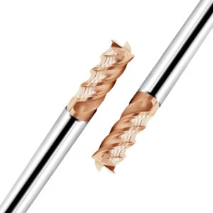
Preventing Chip Residue: How Through-Coolant Designs Enhance Quality in Blind Holes
When tackling blind holes or deep slots, external sprays are virtually useless. As a China carbide milling cutter manufacturer with a strong global presence, we prioritize “through-coolant” channels for high-hardness tools. By directing high-pressure air through internal passages to the tool tip, we create a pressure differential that forces chips out along the flutes. This completely eliminates “chip recutting” at the bottom of the hole.
The impact on surface quality is immediate. In our tests on HRC 50 material at depths exceeding 3*D, through-coolant tools eliminated microscopic tearing at the hole base. While these tools cost more and require specific spindle capabilities, we advise against cutting corners on high-value hardened molds. Combined with the architecture of our HRC 65 end mill bits, this is the most reliable strategy for complex machining scenarios.
Wear Monitoring: How We Guide Clients on Optimal Tool Replacement for HRC 50 Milling
In high-hardness machining, knowing when to stop is a critical skill. The tool life curve for HRC 50 materials doesn’t decline smoothly; it often suffers a “precipitous collapse.” Replace it too early, and your cost-per-part skyrockets. Wait too long, and you risk ruining the surface or scrapping an expensive workpiece due to catastrophic chipping.
Managing this balance requires detecting physical signals on the shop floor. If you are mass-producing high-hardness parts, you should establish “failure benchmarks.” We’ve found that in HRC 50 operations, if the flank wear width (VB value) exceeds 0.15 mm, cutting forces undergo severe fluctuations. At this stage, even if the tool looks okay, it is limping along by sacrificing the workpiece’s integrity.
Sparks and Sounds: Quick Techniques to Identify Micro-Chipping on HRC 65 Edges
Experienced machinists rely on their senses to stop before failure. When machining HRC 50 or higher, the normal sound should be a continuous, low-pitched “hushing.” If you are running an HRC 65 end mill bit and hear intermittent squealing or high-pitched chatter, the edge has likely developed microscopic fractures. The edge is no longer sharp, and friction will turn your sparks from a dull red to a blindingly bright white.
Also, watch your chips. If normally curled strands turn into powdery dust or show distinct burrs, the tool’s “red hardness” has reached its limit. Don’t rely solely on the machine’s load monitor—inertia can mask the fluctuations caused by micro-chipping. Pay attention to the color and direction of the sparks; they are the final distress signals from your milling cutter metal HRC 50.
Assessing Stability via Wear Marks: Remote Diagnosis for B2B Clients
We often receive high-res photos of tool wear from clients in North America and Europe asking why their China carbide milling cutter isn’t performing. Usually, the wear marks act as an “ECG” for the machine’s health. If wear is concentrated on a single edge, or if you see periodic spalling, check your spindle’s dynamic runout or lead screw backlash. In high-hardness work, even 0.01 mm of instability leaves an indelible mark.
Beyond the tool, we examine wear symmetry. Irregular, “jagged” marks indicate a lack of process rigidity. If you are struggling with the finish on an HRC 50+ part, send us microscopic images of the worn tool along with your parameters and drawings. Often, the solution isn’t a more expensive tool, but re-aligning your parameters with your machine’s characteristics. The greatest pleasure in our work is collaborating with peers to uncover the truth behind a tough machining issue.


