


In a CNC shop, the most dreaded sound isn’t the roar of the spindle—it’s that sharp, piercing snap. It’s the sound of an expensive tool shattering while trying to cut steel hardened above HRC60.
Just last month, we handled an emergency for a long-standing client in Boston. They had a batch of D2 mold steel parts that hit HRC62 after heat treatment. They were anxious; their standard thread milling cutters were failing miserably. Edges were chipping off inside the holes, making them impossible to extract. Worse, the NPT thread mill results wouldn’t pass a gauge test. The “Go” and “No-Go” gauges both failed, and the scrap rate was through the roof.
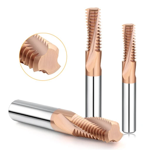
This is a pain point we’ve solved for 15 years as a thread mill cutter manufacturer. When material hardness pushes a tool to its limit, general-purpose tools fail. You don’t just need a “hard” tool; you need an HRC65 thread mill. This tool is engineered from the carbide substrate up to the coating specifically for these extreme conditions.
We often see machinists pull cutting parameters straight from a catalog. But with hardened steel, a radial runout of just 0.01mm or a slight error in the entry arc will instantly destroy a solid carbide thread mill. We didn’t develop these tools for lab data; we built them to survive the intense heat and lateral forces of the real world.
If your workpiece is as hard as stone, why fight a losing battle with aggressive feeding? It’s time to fight hardness with science.
Is your HRC65 thread mill actually cutting, or is it just grinding itself away in agony?

Insights from 16 Years of Manufacturing: The Toughness of HRC65 Thread Mills
When you tackle materials over HRC60, “hardness” and “toughness” are usually at odds. Many peers fall into the trap of thinking a tool just needs to be harder than the part. But experience shows that with materials like SKD11 or CPM, a tool without “fracture toughness” will chip the moment it hits lateral pressure.
We’ve tested countless formulations. The secret to a high-performance HRC65 thread mill isn’t just a high hardness metric. It’s about the stability of the microstructure. The tool body must endure high-frequency vibrations without micro-fracturing.
We see it all the time: an engineer pushes the feed per tooth to save time, only to scrap a $5,000 aerospace component. As a manufacturer, we balance compressive strength with impact resistance. We always tell our clients: sacrifice a little nominal speed for absolute reliability. That “workshop truth” comes from analyzing the wear patterns of tens of thousands of threading cycles.
For HRC60-65 Materials: Preventing Catastrophic Failure in Solid Carbide Thread Mills
Clients always ask: “If two tools are both ultra-fine-grain carbide, why does one shatter instantly?” The secret is the Cobalt (Co) binder and the grain size distribution.
When we formulate the substrate for our solid carbide thread mills, we skip the generic recipes used for woodworking or general machining. For HRC60-65, we use nano-scale tungsten carbide particles. Our specialized sintering process makes the binder act like a high-strength adhesive. It locks every particle in place, preventing “galling” or grain dislodgment while cutting hard threads.
We recently ran a test for a client machining high-hardness bearing steel. We compared a standard market-grade carbide against our proprietary “anti-chipping” blend. Using the same helical interpolation paths, the standard tool showed micro-chipping by the fifth hole. Our blend maintained edge integrity perfectly. It’s about preventing stress concentration so the tool doesn’t break like glass the moment it hits the work.
Coatings Are More Than Color: Protecting Your Thread Milling Cutter in High Heat
In our lab, coatings aren’t for looks; they are thermal barriers. In hardened steel, cutting zone temperatures can spike past 800°C. If your thread milling cutter coating has poor adhesion or low oxidation resistance, it flakes off like old paint. Once that happens, the carbide underneath softens and fails.
We prioritize composite nanostructure coatings. By adding Si or Al, the tool forms a dense aluminum oxide film during the cut. This film is what allows for continuous, stable machining.
I remember a client trying to dry-machine hardened steel with a basic TiAlN coating. It lasted three minutes before thermal fatigue cracked the edge. We stepped in with a nano-composite coating designed specifically for high-hardness jobs. By adjusting the RPM based on our empirical data, we ensured the chips carried the heat away—not the tool. Our data shows that the right coating delays oxidative failure by over 40%. It gives engineers the confidence that their tools won’t “burn out” mid-cycle.
A Guide to Avoiding Pitfalls: Machining High-Hardness NPT Threads
When working with hardened steel over 60 HRC, NPT pipe threads are easily the most vexing challenge. Machining standard straight threads is like “walking in a straight line,” but NPT threads—with their 1.78° taper—are like “walking a tightrope.”
Because of the 1:16 tapered geometry, the radial cutting forces acting on your NPT thread mill change dynamically as the tool goes deeper. Many young engineers fall into a trap: they use the same toolpath algorithms meant for straight threads. The result? Bore diameters that fall out of tolerance or ugly “step marks” on the thread surface.
While supporting oil and gas suppliers in North America, we found their biggest concern is sealing integrity. In hardened materials, even slight vibration leaves “chatter marks.” These aren’t just cosmetic; they are potential leak paths. We believe that when milling NPT threads in hardened steel, you must fundamentally rethink your entry and exit points. Don’t expect a single-pass operation to cut it. To guarantee a leak-proof seal, you need a conservative finishing strategy.
Why Standard Machining Parameters Fail in NPT Tapered Cutting
Many shops try to use the standard cutting speeds from a tool catalog. This is a recipe for disaster. Catalog parameters are usually designed for constant-diameter holes. In a taper, the surface area of the side cutting edges engaged in the cut is constantly changing.
This fluctuating load causes the thread milling cutter to deflect. In hardened materials like 4140 or H13, this micron-level deflection is amplified exponentially. Suddenly, your “Go” gauge won’t go, or your “No-Go” gauge won’t hold.
We’ve analyzed hundreds of failures and found that 80% of issues stem from poor chip evacuation and uneven cooling. Standard speeds at the bottom of a tapered hole cause heat to build up because chips are trapped. If you use a constant feed rate, the tool tip at the narrow bottom faces pressures several times higher than at the top. We advise reducing nominal cutting speeds by 20%–30% and using a multi-pass strategy to manage that stress.
The Helical Interpolation Strategy for High-Pressure Sealing
To achieve zero leakage at 3000+ psi, we’ve developed a specialized helical interpolation scheme for high-hardness materials. The two most critical techniques for your solid carbide thread mills are “arc entry” and “overlap cutting.”
Plunging vertically at the start point is a mistake. The high elastic modulus of hardened steel creates a massive recoil force against the tool. This leaves a tiny indentation—often invisible—that ruins the seal. Instead, we start at the center and arc smoothly into the thread. This ensures a seamless transition of cutting forces.
Our programs for Western clients typically use at least two finishing passes. The first pass calibrates the tapered geometry. The second pass—a “spring pass” or “skimming” operation—uses minimal radial engagement to wipe away any taper deviations caused by tool deflection. It adds a few seconds to the cycle, but it’s the only way to guarantee a perfect seal on expensive, precision-hardened parts.
Engineer-to-Engineer: Maximizing Solid Carbide Thread Mill Life
In our industry, we all want efficiency, but blindly pushing parameters is counterproductive. When you’re holding a high-end HRC65 thread mill, its service life depends on your microscopic control over the cutting load.
Most abnormal wear doesn’t happen because the material is too hard; it happens because of “alternating stresses” from poor step-over strategies. We recommend fine-tuning your spindle speed to avoid resonance zones rather than forcing a tool through an unstable cut.
You must also be sensitive to “initial wear.” If you’re machining HRC60+, implement a strict inspection protocol. Once you see microscopic chipping over 0.02 mm, cutting forces multiply. If you don’t adjust your offsets or swap the tool immediately, you’ll trigger a chain reaction that ends in a broken tool. Unlocking a tool’s potential requires precise “tailoring”—like ensuring the retraction at the thread root is perfectly smooth.
Why We Recommend Dry Machining for HRC65 Materials
This might sound counterintuitive, but for an HRC65 thread mill, we often advise against traditional emulsion-based coolants. Water-based coolants are the primary cause of thermal cracking.
When the cutting zone spikes in temperature and coolant hits the edge intermittently, the rapid expansion and contraction create massive internal stress. We’ve found that dry machining—combined with high-pressure air—can extend tool life by more than 100%.
High-pressure air evacuates chips effectively, preventing “chip re-cutting” and secondary hardening damage. It also keeps the cutting zone at a stable, elevated temperature, allowing the carbide to maintain its “red hardness” equilibrium. If your machine has a cold-air blower, use it. Letting red-hot chips blow away is much safer than letting them entangle the tool in a bath of coolant.
Best Practices for Tool Entry (Arc-in) and Multi-Pass Cutting
If you are still using a “Straight Entry” engagement, your thread mill cutter manufacturer is likely getting a lot of repeat business from you. We advocate the “Arc-in” technique. This allows the cutting force to increase linearly from zero, pre-loading the tool body rather than shocking it.
Regarding multi-pass cutting: do not attempt a single full-depth cut on high-hardness threads. Dividing the depth into two or three lateral passes reduces the load on the spindle and drastically improves surface finish.
We recommend allocating 60% to 70% of the material to the first pass, leaving the rest for the finisher. It might cost you a few extra seconds per part, but it makes the process predictable. In precision CNC work, the cost of one snapped tool and a scrapped part far outweighs a slightly longer cycle time.
Why Choose a Specialized Thread Mill Cutter Manufacturer Over a General Supplier?
In our factory lab, we receive inquiries from around the world every day. Most clients share the same frustration: they’ve bought expensive tools from giant, general-purpose catalogs, yet the tools fail inconsistently in hardened steel.
As a specialized thread mill cutter manufacturer, we know why. General-purpose tools are designed for the “80% solution”—aluminum, 1018 steel, or soft alloys. Their geometries are adequate for those, but they lack the extreme rigidity required for heat-treated, hardened steel.
Our approach is “less is more.” While a general supplier offers 50,000 different items, we focus entirely on the microscopic stress dynamics of high-hardness machining. We tune the tool’s core-to-diameter ratio based on your specific machine rigidity and workpiece hardness. A specialized tool might not look “all-encompassing” on a data sheet, but it prevents the late-night calls about broken tools and scrapped parts. That operational certainty only comes from real-world field experience.
Customized Geometry: Why a “Thin Edge” Is a Cardinal Sin for HRC65
Many engineers want a “light and brisk” cut, so they reach for the sharpest edge possible. In hardened steel, that “thin edge” is the start of a nightmare. When we develop solid carbide thread mills for HRC65, we intentionally apply a negative chamfer or micro-honing.
It sounds counterintuitive—why make a tool “duller”? Because at 60+ HRC, a razor-sharp edge lacks the structural integrity to survive the first impact. It chips the moment it hits the part, leading to rapid abrasive wear. We’ve tested this: a sharp-edged tool with a large rake angle usually fails after fewer than three holes. Our reinforced, honed edge might show slightly higher initial resistance, but it distributes force across a robust substrate. In hardened steel, structural integrity beats a sharp edge every time.
Enhancing Finish Through Secondary Fine Grinding
If you look into the flutes of a high-quality thread milling cutter and see a mirror finish, that’s the result of secondary fine grinding. We don’t do this for aesthetics; we do it to kill friction.
Chips in high-hardness materials carry immense thermal energy. If the flute surface is rough, those chips act like sandpaper, abrading the tool and causing “heat soak” or tool burning.
Our North American clients demand tight surface finishes. By fine-grinding the flutes, we eliminate microscopic serrations along the edge. This reduces lateral friction and vibration. Often, a part fails a “Go/No-Go” gauge test not because of dimensions, but because of surface waviness or burrs. Our fine-grinding process is designed specifically to solve those surface-integrity issues.
Real-World Case Study: Troubleshooting NPT Thread Mill Failures in HRC62 Steel
Machining NPT threads in hardened mold steel is arguably the most failure-prone task in a shop. Last year, a client was working on HRC62 cold-stamping dies. They needed NPT ports for high-pressure hydraulic fittings. The problem? The NPT thread mill worked perfectly on the first part, but by the third part, the taper was completely off.
This is classic failure logic. Once you cross HRC60, material yield strength undergoes a qualitative change. The tool is no longer just a cutter; it’s a “precision instrument” fighting extreme pressure. If your threads are too tight at the shoulder or fail a leak test, simply bumping your “D-value” (offset) is just a band-aid. You have to re-evaluate the rigidity of the entire setup.
Failing the Gauge Test? Check These Three Variables
When the Go/No-Go gauge fails, don’t just blame the tool. Check these three “let-down” variables:
-
Effective Overhang: If you’re using a long-neck tool, even 5mm of extra overhang increases deflection exponentially in 60 HRC steel. Try shortening your clamping or switching to a high-rigidity heat-shrink holder.
-
Interpolation Feed Consistency: Your programmed linear velocity might be constant, but in small holes, the differential between the tool center and the cutting edge is massive. You might be accidentally overloading the “feed per tooth.”
-
Pilot Hole Roundness: If the pilot hole is tapered or elliptical after drilling, the thread milling cutter will face uneven forces. If you suspect deflection, add a “spring pass”—a second pass with zero radial allowance. It will immediately show you if your system is flexing.
Boosting Output by 30% Through Program Optimization
True cost isn’t the price of the tool; it’s the downtime and scrap risk. To get more out of a single HRC65 thread mill, look at your “entry path.” If you’re using a blunt, direct-entry move, switch to a “helical arc entry.” Reducing the engagement angle at the moment of impact can extend tool life by over 20%.
Also, look at chip evacuation. If you use compressed air, ensure it’s aimed to sweep the bottom of the hole to prevent “re-cutting” of fine chips. We’ve found that switching to a multi-layer, small-step strategy—even if it seems slower—reduces thermal fatigue. This often boosts the number of finished parts per tool by 30%.
Every shop has unique machines and material batches. If you’re struggling with vibration, chipping, or NPT taper issues, let’s talk. We can look at your blueprints and material specs to find a manufacturer-level solution that works.


