


To be honest, when the needle on the hardness tester hits HRC65, most machine shops just shake their heads. In my 15 years on the shop floor, I’ve stood beside countless CNC centers watching “hardened steel” tools scream for mercy before crumbling into dust within minutes. When you’re machining materials that approach the physical limits of carbide, the margin for error is zero.
I recently helped a precision mold maker in the U.S. with a deep-cavity project using quenched D2 steel. It validated a hard truth: machining HRC65 isn’t about brute force. It’s about the absolute mastery of heat and rigidity. Many shops fail because they use a standard milling cutter for hardened steel and fall into a “death spiral”—slowing the feed rate to “save” the tool, which only causes heat to build up and destroy the cutting edge faster.
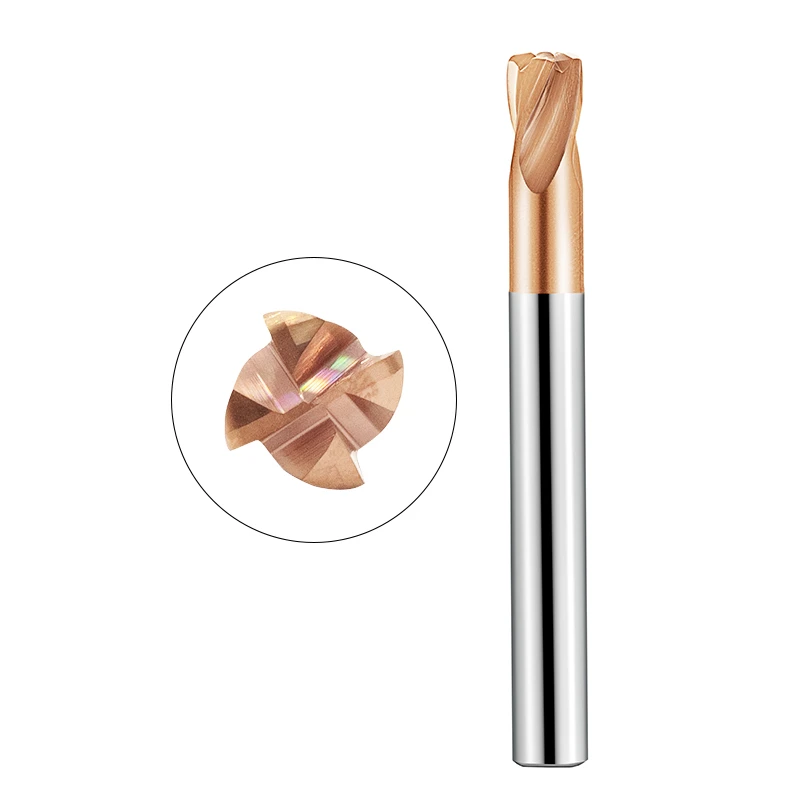
Even with top-tier hrc65 carbide milling cutters, if you ignore the balance between coating toughness and chip evacuation, you won’t survive a single shift. Especially when using a roughing milling cutter, navigating the edge between high metal removal rates and catastrophic chipping is a survival skill we’ve had to master.
Today, we’re skipping the textbook theories. I’m sharing real-world experience earned at the cost of thousands of scrapped milling cutter bits. We’ll discuss why standard geometries fail under thermal shock and when you actually need custom carbide milling cutters to hold a 0.01mm tolerance.
When facing metal that feels like machining glass, have you ever watched a $300 tool vanish in a puff of smoke because of one tiny parameter fluctuation?
Severe Thermal Cracking in HRC65 Carbide Milling Cutters
When you hit HRC65, heat is your primary enemy. In standard steel, chips carry the heat away. In high-hardness materials, cutting forces explode, and frictional energy can drive zone temperatures past 800°C. We’ve observed that even the toughest carbide substrates develop microscopic thermal cracks due to differential expansion. These cracks start at the edge and crawl inward; once they cluster, the tool fractures without warning.
We’ve put failed hrc65 carbide milling cutters under high-magnification microscopy in our lab. The killer isn’t usually abrasive wear—it’s substrate spalling from thermal fatigue. If your tool develops “serrated” chipping after five minutes, your feed rate probably isn’t the problem. Your thermal stress management is. At HRC65, the material’s tensile strength is pushed to the limit. Any spike in the thermal cycle results in a “total loss” for the operation.
Why Traditional Coolants Fail at HRC65
Last year, we provided on-site support for a mold shop in Chicago machining hot-work die steel at HRC65. To prevent “burning” the tool, the operator cranked the high-pressure internal coolant. The tool snapped in less than 30 seconds. The fracture was clean—a textbook case of thermal shock. This is the “Quenching Effect.” Cold fluid hitting a red-hot cutting edge creates violent alternating stresses in the alloy. These forces are far more destructive than the actual cutting pressure.
In these high-hardness ranges, liquid coolant can’t even reach the interface between the tool tip and the workpiece. Instead, the splashing creates localized temperature swings. This unstable equilibrium is what causes the edge to chip. We told the operator to kill the pump and switch to a “dry” strategy. As it turns out, a constant high-temperature environment does less damage than the shock of uneven cooling.
The Fix: Heat-Resistant Coatings and Dry Machining Strategies
Since liquid cooling is off the table, we build a “thermal barrier” on the tool itself. This is why we use advanced nanocomposite coatings like TiSiN for any milling cutter for hardened steel. Under high heat, this coating forms a dense SiO2 layer. It provides lubrication, but more importantly, it blocks heat from migrating into the carbide substrate. If your coating can’t handle oxidation at 1000°C, the substrate quality doesn’t matter.
In practice, use compressed air to clear chips. The logic isn’t to lower the temperature, but to use powerful airflow to blast high-temperature chips away before “re-cutting” occurs. When we move clients to air-cooling and high spindle speeds, we often see tool life jump by 300%. Shifting your mindset from “killing the heat” to “managing the heat” is the turning point for HRC65 success.

Challenge 2: Balancing MRR and Tool Life with a Roughing Milling Cutter
When roughing out HRC65 molds, shop supervisors often face a dilemma: chase a faster delivery or protect the expensive tooling. At this hardness, increasing the MRR isn’t as simple as cranking up the depth of cut. Excessive radial forces travel straight through the roughing milling cutter to the spindle, causing the whole system to resonate. If your setup isn’t rigid, even the best carbide substrate will fail from high-frequency fatigue.
In our shop, we view the rougher as a “system balancer.” Blindly increasing the Ap to shave seconds off a cycle usually leads to spindle load spikes or bearing damage. We tell our clients: stop looking at “depth per pass” and start looking at “volume removed per minute.” Moving from traditional deep cuts to high-dynamic strategies is the core lesson we’ve learned from years of broken tools in the field.
The Trade-off: High Removal Rates vs Catastrophic Tool Failure
I often see seasoned machinists in the U.S. and Europe try to boost efficiency by increasing the Ae. In HRC65, this “chokes” the tool. We once saw an automotive mold project fail because an aggressive feed rate caused heat to build up faster than the chips could clear. Within seconds, the tool didn’t just wear out—it snapped, and the impact cracked the workpiece.
Spindle overload alarms are your machine’s distress signals. At HRC65, cutting force increases non-linearly with the feed rate. Instead of redlining your roughing milling cutter, optimize the feed per tooth. You want that “sweet spot” where the chips are a consistent bluish-purple and the spindle load is stable. This isn’t just about the tool; it’s about the stability of your entire production line.
Optimizing the Toolpath for Deep Cavities
For deep cavities, we abandon large depths of cut. We recommend a HFM strategy: shallow Ap combined with a high feed rate. This redirects cutting forces vertically toward the spindle axis, which significantly reduces lateral deflection. When you optimize the path this way, the jarring screech of hard machining is replaced by the steady hum of smooth chip formation.
To clear corners without snapping a tool, use trochoidal or dynamic milling paths. These keep the tool’s engagement angle constant, preventing the “load spikes” that happen when a tool hits a corner and the contact area suddenly doubles. It takes a bit longer to program, but when you’re tackling HRC65, it’s the only way to ensure a scrap-free process.
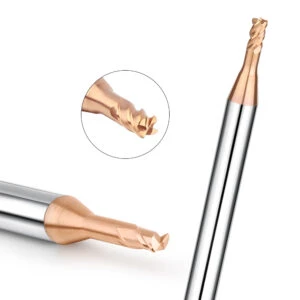
Challenge 3: Deflection and Inconsistent Precision in Milling Cutter Bits
Few things are more frustrating than hitting the finish stage on an HRC65 part only to find the dimensions are off. In narrow slots or deep cavities, the material’s hardness pushes back against the cutting edge with incredible force. This creates “tool push-off” or deflection. Even if your spindle runout is under 2 microns, if your milling cutter bits lack the rigidity to fight back, you’ll end up with tapered walls—wider at the bottom than the top.
Field testing shows this deflection is non-linear. In soft steel, you might not notice it. In a “hard-on-hard” HRC65 scenario, even 0.01mm of deflection ruins the surface finish. This doesn’t just mess up assembly; it causes uneven loading on the edge, which leads to chipping. The fix isn’t just “adding compensation” in the offset; it’s about increasing the rigidity of the system at the source.
Why Standard Milling Cutter Bits Struggle with HRC65 Rigidity
Many shops grab a long-flute tool from a standard catalog and think a “finishing allowance” will save them. But standard milling cutter bits often sacrifice rigidity for versatility, using high L/D ratios (length-to-diameter) that act like a slender lever under pressure. We saw this in a medical mold project: a standard tool hit resonance at the bottom of a deep slot, leaving wave-like chatter marks across the workpiece.
The root cause is the core diameter. Standard tools leave huge flutes for chip evacuation, which weakens the tool’s core. In HRC65 finishing, the chips are fine powder—you don’t need those massive flutes. A small core diameter can’t handle the load. This reality forced us to re-evaluate tool geometry entirely for high-hardness finishing.
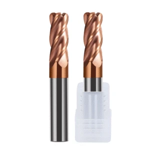
The Solution: Short Flutes and Tapered Necks
To hold micron tolerances in HRC65, we use two principles: “subtractive” and “additive” geometry. First, we shorten the flute length. Every time you double a tool’s overhang, its rigidity drops exponentially. Using the shortest possible flute increases the core’s cross-sectional area and kills deflection. This simple change usually jumps the surface quality by a full grade.
Beyond short flutes, we use “Tapered Neck” designs. This maximizes strength at the root of the tool while keeping the tip clear of the workpiece walls. A tapered neck absorbs high-frequency vibrations that a straight neck can’t. While custom carbide milling cutters with these features cost more to produce, the stability they provide is invaluable. In HRC65 machining, rigidity is your lifeline—and geometry is how you protect it.
Challenge 4: Premature Corner Wear on Milling Cutters for Hardened Steel
When you’re cutting HRC65, the most vulnerable part of the tool isn’t the main edge—it’s the sharp corner. It’s the easiest spot to overlook, but it’s almost always where the failure starts. When we examine a failed milling cutter for hardened steel, we usually see microscopic chipping at the tip. Because the corner is the point where heat dissipation is slowest and stress concentration is highest, it becomes a thermal bottleneck. Once the cutting force exceeds the carbide’s rupture strength, you get “tip chipping.”
This wear triggers a chain reaction. On the shop floor, we’ve seen a tiny 0.05mm chip at the tip cause cutting resistance to explode, leading to violent vibration. In HRC65 machining, protecting the corners is the only way to save the tool. If you see white “burn” marks on the part or hear a piercing, high-pitched screech, your corners are likely seconds away from catastrophic failure. You have to intervene early by adjusting your geometric compensation to stop this irreversible damage.
The “Chipping” Nightmare: Why the Corners Go First
When machining mold steels like D2 or H13 at HRC65, we use microscopes to track edge wear. These alloy steels are packed with carbide particles that act like microscopic hard nodules, constantly bombarding the edge. For a standard sharp-cornered tool, this bombardment is destructive. Because the volume at the sharp tip is so small, it can’t absorb the impact energy like the rest of the tool body.
We’ve seen the protective coating on sharp corners spall off in less than ten minutes due to thermal fatigue, followed immediately by brittle fracture. This “chipping nightmare” gets even worse with deep cuts or fluctuating feed rates. Operators often tell us, “My parameters are exactly the same as usual, but the tip keeps failing.” The reason is the shear strength of HRC65—the stress concentrated at that single point is just too high for a sharp tip to handle.
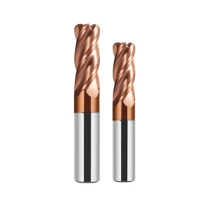
The Advantage of Radius End Mills for Hardened Steel
To fix this, we strongly recommend ditching flat-bottom mills for radius end mills—or “bull-nose” cutters. The logic for using this type of milling cutter for hardened steel is simple: by adding a small corner radius (R-angle), you disperse the cutting force from a single “point” across a smooth “arc.” This doesn’t just strengthen the edge; it creates a wider path for heat to escape, lowering the temperature at the tip.
In the field, even a 0.2mm or 0.5mm radius creates a qualitative leap in impact resistance. In our HRC65 tests, bull-nose cutters increased tool life by 40% or more compared to flat-bottom designs. You might worry about the residual material left in the corners, but when you look at the total cost and the reduced downtime from tool changes, the trade-off is worth it. For ultra-hard materials, the bull-nose cutter is the “evergreen” solution for a stable line.
Challenge 5: When Standard Tools Hit the Limit—The Need for Custom Carbide Milling Cutters
In a CNC career, you’ll eventually hit “gray areas” that standard catalogs don’t cover. When you combine HRC65 hardness with thin walls, high L/D ratios, or complex spatial surfaces, off-the-shelf tools just don’t cut it. Often, the problem isn’t the machine—it’s the tool’s inability to sync with specific resonant frequencies. Instead of wasting time and scrapping expensive workpieces with trial-and-error, it’s smarter to redesign the geometry from the ground up.
At this hardness, the balance between vibration resistance and rigidity must be in perfect harmony. This is where custom carbide milling cutters prove their value. Customization is more than just changing a diameter; it’s a total optimization of the substrate, the helix angle, and the edge reinforcement. Our experience shows that a bespoke tool can solve problems that have plagued a shop for weeks, turning an “impossible” task into a stable production run.
Case Study: Solving Aerospace Geometry in Hardened Parts
A few years ago, we handled a thorny aircraft component project. The client needed to machine narrow, precision slots with a slight draft angle into ultra-high-strength steel hardened to HRC65. They tried every major brand’s standard tooling, and every attempt failed—either the tool snapped at the shank due to excessive overhang, or the slot walls were covered in chatter marks. In aerospace, there is zero room for chatter; those marks become “stress risers” that can cause part failure.
We went to the client’s engineering center and captured real-time vibration data from the spindle. We found that conventional tools with constant helix angles were hitting the workpiece’s natural resonant frequency. We scrapped the off-the-shelf options and designed a custom carbide milling cutter specifically for that slot. By tapering the neck and optimizing the coating, we held a 0.005mm tolerance and cut the per-piece cost by 40%. Result-oriented customization is the only true shortcut for complex parts.
How Custom Carbide Milling Cutters Solve Vibration Issues
Why do custom tools give a better finish on HRC65? The secret is “asymmetrical design.” Standard tools have evenly spaced edges that generate periodic impact loads, which induce high-frequency chatter. Our custom carbide milling cutters use variable indexing (uneven tooth spacing) and variable helix angles. This disrupts the resonance cycle, ensuring each edge hits the material at a different time, physically “canceling out” the vibration.
When you run an asymmetrical tool, you can hear the difference: the piercing metallic screech turns into a steady, continuous hum. We’ve shown clients that simply by adjusting the helix gradient, we can drop the surface roughness (Ra) of an HRC65 part from 0.8 to below 0.2. This pursuit of stability adds complexity to the design, but for high-value, high-hardness parts, it’s the most reliable way to achieve a flawless finish. In high-end manufacturing, stability is the ultimate form of efficiency.


