


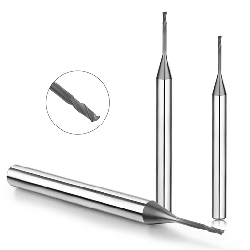
We recently handled a precision graphite electrode project where the client faced inconsistent results despite standard tooling, rigid CNC machines, and verified programs. Initial workpieces showed clean surface finishes, but edge chipping, fine airborne dust, and accelerated tool wear soon appeared. The client assumed the problem was premature tool failure. However, analyzing the cutting zone revealed that tool age was not the culprit. The true issue stemmed from how the graphite material was being removed under the active cutting edge.
This scenario is common across CNC graphite machining facilities. Operators often adjust spindle speed, feed rate, or depth of cut without understanding graphite chip formation, yielding only temporary fixes. Graphite does not shear continuously like ductile metals; it undergoes micro-brittle fracture. Localized cutting forces trigger rapid crack initiation and propagation, shedding fragmented particles instead of curled ribbons. Machining success directly depends on controlling crack propagation, chip fracture mechanics, and graphite microstructure interactions.
Mastering the graphite milling cutting mechanism begins with the contact zone between the cutting edge and the graphite substrate. Tool geometry governs the edge entry angle, cutting force distribution, and localized stress fields. The geometry of a graphite end mill dictates how micro-cracks form and where chips evacuate. Because of brittle fracture mechanics, removed graphite forms fine dust, irregular grains, or small fragments rather than continuous chips.
For this reason, process diagnostics must look beyond simple tool wear indicators. Graphite chip type, particle size distribution, and evacuation behavior reveal the true state of material removal. Erratic chip formation leads to severe edge breakout, poor surface roughness, and rapid abrasive wear on the tool flutes. High-friction contact also alters cutting zone temperatures, which destabilizes edge retention and dimensional accuracy over extended cycles.
Rather than offering generic machining tables, this guide breaks down the physics of chip formation in graphite milling. We examine why graphite fractures along grain boundaries, how micro-cracks coalesce into chips, and what specific chip morphologies indicate. We also explore how tool geometry, cutting loads, and thermal build-up alter the fracture process to directly impact tool life and part tolerance.
If your shop deals with unpredictable edge chipping, excessive graphite dust, or short tool life despite using standard parameters, the issue is rarely the machine code. The real solution lies in mastering the fundamental cutting mechanics of graphite.
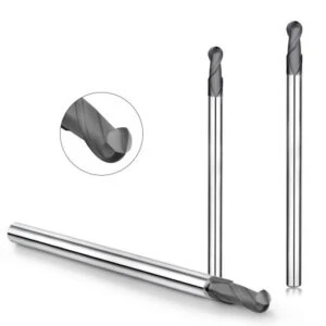
Graphite Chip Formation: How Are Chips Formed During Graphite Milling?
When machining graphite electrodes, the most critical moment is the instant the cutting edge engages the material. In a recent batch of micro-electrodes, fine debris accumulated inside narrow slots while micro-chipping appeared along sidewalls. Tool condition, clamping rigidity, and code were verified, pointing the issue directly to the material removal mode. Graphite does not shear plastically like steel; localized stress concentration triggers crack initiation, breaking particles off the workpiece to govern graphite chip formation.
We analyze this cutting action as a continuous cycle: initial engagement, load build-up, crack propagation, and particle ejection. The dust and fine fragments visible on the machine bed reflect this exact sequence. Grain size, internal porosity, and cutting edge sharpness directly dictate fracture behavior. Reliable process monitoring requires evaluating chip morphology alongside surface finish, edge integrity, and tool wear.
Graphite Milling Mechanism: The Basic Material Removal Process
Understanding the graphite milling mechanism begins at the contact zone between the tool edge and the graphite substrate. During slotting operations, each tooth impact generates localized stress fields within the workpiece. Once this stress surpasses material tensile limits, micro-cracks propagate along grain boundaries and pore defects to release particles. This fracture-dominated behavior defines the entire removal process.
The cutting edge essentially drives controlled crack propagation ahead of the tool path. Tool entry angle, instantaneous chip thickness, edge hone, and part clamping dictate crack direction. Stable cutting conditions produce uniform, fine particulate debris across cycles. Uncontrolled load spikes cause erratic particle fragmentation, severe edge breakout, and surface pitting on finished walls.
Graphite Chip Formation Mechanism: How the Cutting Edge Forms Chips
During high-precision electrode milling, abnormally coarse fragments can appear even without visible tool edge breakdown. Microscopic inspection shows this stems from subtle shifts in edge contact mechanics. The cutting edge concentrates compressive and shear stresses rather than shearing a continuous ribbon. Micro-cracks spread forward and downward, causing localized block detachment via the core graphite chip formation mechanism.
When chip fragments suddenly turn coarse or irregular, machine operators must check more than just dust collector output. Inspect the cutting edge micro-geometry, edge chipping locations on the part, and spindle load fluctuations. In precision graphite milling, stable crack containment matters more than aggressive material removal rates, as uncontrolled cracking damages part edges instantly.
Graphite Brittle Machining: How Material Brittleness Affects Chips
Workpiece grade heavily influences fracture dynamics during graphite brittle machining. Ultrafine-grain graphite yields small, consistent dust, whereas coarse-grained or high-porosity grades fracture into larger, irregular flakes under identical parameters. These internal voids and binder boundaries alter crack paths, making graphite removal fundamentally different from ductile metal cutting.
When chip size shifts unexpectedly, evaluate graphite fracture properties before altering speeds and feeds. In production, we evaluate debris morphology, corner retention, and flank wear simultaneously for precise root-cause diagnosis. Because brittle materials amplify minor cutting shocks into major part defects, managing fracture paths is essential for tight tolerances.
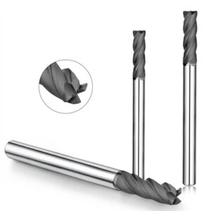
Graphite Milling Cutting Mechanism
In precision electrode production, shops often see sudden edge chipping and excessive debris across identical machines, tools, and CAM programs. Rather than blaming tool life right away, we examine the tool-workpiece interface to see how material detaches. Graphite milling does not rely on continuous plastic shear; it depends on contact stress, micro-crack initiation, and brittle fracture. Mastering the graphite milling cutting mechanism provides the real fix for these erratic machining issues.
Our field diagnostics break this process into three phases: edge loading, crack initiation sites, and propagation trajectories. Graphite grain structure, pore distribution, density, and cutting edge sharpness dictate each stage. While raw debris alone does not pinpoint the exact failure mode, evaluating the cut zone, edge integrity, and flank wear reveals the root cause quickly.
Graphite Cutting Mechanism: Interaction Between the Cutting Edge and Graphite Material
During narrow slotting and fine-detail milling, initial tool entry determines how the substrate fractures. A sharp edge concentrates heavy compressive, shear, and tensile loads into a microscopic zone. As the flute rotates forward, stress fields shift, causing micro-cracks to form along grain boundaries and internal voids. This localized mechanical interaction forms the core of the graphite cutting mechanism.
When consistent micro-chipping appears along part corners, check beyond catastrophic tool failure. Inspect edge hone micro-wear, tool engagement angles, and part chatter, as all three alter contact stress fields. Small diameter end mills are sensitive to cutting loads; minor tool runout quickly turns stable chip shearing into erratic substrate breakout.
Graphite Brittle Machining: Crack Initiation and Brittle Fracture
Different graphite grades show vastly different fracture mechanics under identical feeds and speeds. Ultrafine grades produce fine powder, while porous, coarse-grained grades yield chunky flakes and corner blowout. When tool loads exceed material tensile thresholds, micro-cracks propagate along grain boundaries. This rapid fracture dynamic is the defining principle of graphite brittle machining.
Do not assume harder graphite grades always cause worse chipping; microstructure and tool load distribution matter just as much. When edge chipping spikes, evaluate bulk density, grain size, edge quality, and edge wear together. For EDM electrodes, the main goal is keeping crack propagation inside the cut envelope to prevent subsurface damage.
Graphite Chip Formation: How Crack Propagation Leads to Chip Formation
In one electrode project, a sudden spike in debris particle size coincided with rougher sidewall finishes. Analysis showed the problem was not chip evacuation, but an altered fracture path through the graphite matrix. As the cutting edge advances, micro-cracks drive forward until reaching a free surface, breaking loose discrete grains. Controlled crack propagation directly dictates consistent graphite chip formation.
Evaluating chip morphology requires looking beyond dust extraction volume. Micro-powder, irregular flakes, and blocky chunks each indicate a different material failure mode. If cracking stays confined directly ahead of the edge, part dimensions remain true. When cracks travel below the cut line, severe edge chipping and pit marks ruin final tolerances.
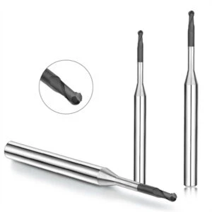
Graphite Chip Types: What Kinds of Chips Are Produced During CNC Graphite Milling?
In precision electrode production, classifying milling debris by eye reveals critical cutting dynamics. During slot roughing, CNC mills discharge coarse granular debris, whereas finishing passes generate fine airborne powder. This transition reflects how localized cutting loads dictate material failure. Evaluating particle size, geometry, fracture uniformity, and surface finish helps determine the specific graphite chip type and diagnose cutting zone stability.
Never judge graphite milling by aiming for large chips or minimal dust. Graphite undergoes brittle micro-fracture governed by grain size, porosity, cutting edge sharpness, and instantaneous cutting force. Our priority is monitoring whether debris morphology remains stable across cycles. Sudden particle enlargement accompanied by edge chipping, surface pitting, or rapid flank wear indicates an uncontrolled fracture process.
Fine Graphite Chips: Fine Particles and Powder-like Chips
Finish milling intricate electrodes with micro-tools naturally produces fine, airborne particulate. This dust indicates that micro-cracks propagated rapidly over microscopic distances ahead of the cutting edge, breaking the graphite matrix into grains. Generating fine graphite chips during light finishing passes is normal provided part sidewalls remain smooth and corner profiles stay sharp.
However, a sudden surge in micro-powder during steady cycles signals serious cutting edge degradation. Excessive pulverization points to severe flank wear, rubbing, and secondary debris re-cutting. When fine dust fails to evacuate immediately, it gets trapped between the flute and workpiece, increasing cutting friction and thermal loads in the cut zone.
Fragmented Graphite Chips
Blocky, flake-like fragments typically form during roughing passes or when milling coarse-grain graphite grades. Deep cavity roughing naturally generates larger chunks because higher chip loads drive deeper fracture lines. As long as these fragmented graphite chips evacuate cleanly without tearing out part corners, they represent an efficient, high-volume brittle fracture mode.
Sudden shifts toward oversized, irregular chunks during light passes require immediate intervention. Irregular fragments paired with corner breakout mean micro-cracks have propagated past the programmed cut boundary into the finished part. For tight-tolerance graphite electrodes, maintaining controlled fracture boundaries matters far more than pushing peak material removal rates.
Relationship Between Graphite Chip Type and Material Fracture Behavior
Decades of machining different graphite grades show a direct link between debris morphology and substrate microstructure. Grain size, binder matrix strength, bulk density, and porosity dictate how micro-cracks propagate under load. Comparing distinct graphite chip types across ultrafine and coarse grades proves that material properties fundamentally govern fracture boundaries and chip shapes.
To diagnose milling stability from debris, track three key indicators: sudden particle size shifts, erratic fragment geometry, and corresponding changes in edge chipping or tool wear. Evaluating chip morphology alongside part quality provides actionable diagnostic data. The debris on the table is the direct outcome of how the cutting edge drives crack initiation and brittle fracture.

How Does Graphite End Mill Geometry Affect Chip Formation?
Switching tool designs during graphite electrode milling changes chip morphology, edge finish, and tool life—even with identical feeds and speeds. When cutting narrow ribs and micro-features, rake angle, clearance angle, edge hone, flute profile, and helix design dictate how cutting edges engage the workpiece. In our CNC testing, graphite end mill geometry serves as an active control parameter for stress distribution and crack initiation.
Never treat end mill selection as a simple catalog lookup. Varied tool geometries alter localized stress fields and chip evacuation paths. Because graphite removes via brittle micro-fracture, slight geometric shifts heavily impact part corner retention. We diagnose tooling stability by correlating chip size, part breakout, and flank wear rather than evaluating isolated tool features.
Graphite End Mill Geometry and Cutting Edge Entry Behavior
When contouring precision electrode details, the initial contact of the cutting edge determines the fracture path. A sharp, well-honed edge enters smoothly, concentrating stress directly ahead of the cut zone. Poor edge geometry or excessive runout creates blunt impact loads, triggering erratic subsurface fractures. Field data proves that proper graphite end mill geometry stabilizes edge entry dynamics far better than simply changing tool diameters.
When periodic micro-chipping appears along part edges, inspect edge sharpness and dynamic runout immediately. Small diameter end mills transmit load spikes directly into brittle graphite corners, turning clean fracture into edge blowout. Match edge prep and tool geometry to grain structure, feature geometry, and surface finish goals instead of using generic carbide cutters.
How Flute Geometry Affects Graphite Chip Evacuation
In deep cavities and narrow slotting, rapid debris removal is just as critical as initial chip detachment. Graphite fractures into fine, abrasive dust; without open flute troughs and polished gullets, particles pack tightly around the tool body. This causes severe secondary re-cutting, elevating cutting temperatures and abrasive wear. Proper flute geometry ensures ample chip capacity and unrestricted evacuation paths.
Deep cavity milling demands active chip extraction rather than passive flute containment. If performance drops and tool wear accelerates in deep cuts, inspect flute volume and dust extraction airflow. Optimized flute design expels abrasive graphite dust instantly, preventing the tool from grinding trapped debris against finished sidewalls.
The Relationship Between Helix Angle and Graphite Chip Formation
Altering the helix angle changes the contact arc length, axial force balance, and particle evacuation trajectory. As the cutting edge enters graphite along the helical path, it modulates cutting resistance and micro-crack paths. Evaluating how the helix angle influences chip behavior requires balancing shear efficiency with axial lifting forces.
Lower helix angles reduce axial pull on thin-walled ribs, while higher helix angles clear debris faster from deep cavities. Select helix structures by analyzing tool diameter, reach, cut depth, and material grain density together. An optimal helix angle balances smooth cutting forces with reliable chip evacuation to prevent part corner chipping.
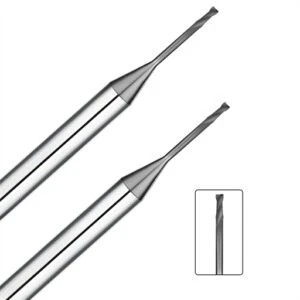
Graphite Cutting Force: How Does It Affect Chip Formation?
In deep-slot electrode milling, cutting load spikes frequently trigger erratic debris and corner chipping as cut depth increases. Machining brittle graphite means mechanical loads affect more than just tool deflection; they actively reshape internal stress fields to dictate crack initiation. Real-time monitoring of graphite cutting force provides direct insight into particle fragmentation, debris morphology, and part edge stability.
When chip size shifts under identical feed rates, look beyond simple spindle RPM settings. Real cutting loads reflect axial depth of cut, instantaneous chip thickness, cutter runout, grain density, and machine rigidity. In our machine shop, we correlate cutting acoustic signatures, spindle load meters, debris consistency, and flank wear to catch force anomalies before they cause part scrap.
Graphite Cutting Force and Crack Formation
During micro-rib and thin-wall milling, sharp cutting edges concentrate mechanical loads into narrow contact zones. As edge pressure accumulates past the material’s fracture limit, micro-cracks initiate at grain boundaries and internal pores. The primary goal is keeping crack propagation confined strictly within the designated shear zone, directly linking graphite cutting force to stable crack generation.
When troubleshooting edge breakout, inspect dynamic tool runout, edge hone degradation, and abrupt radial step-overs. Small-diameter end mills transmit load spikes directly into unsupported corners, driving fractures below the programmed tool path. Maintaining controlled, low-amplitude cutting forces prevents subsurface micro-cracks from ruining finished electrode contours.
How Do Cutting Forces Affect Graphite Chip Morphology?
Evaluating shop-floor debris reveals immediate shifts in localized cutting loads. When roughing loads climb excessively, uniform granular dust quickly gives way to oversized, irregular fragments. Increasing instantaneous mechanical stress drives deeper micro-crack penetration through the matrix, shifting the resulting graphite chip type from fine powder to blocky debris.
If debris transitions abruptly from fine grains to chunky flakes, check both workpiece walls and edge sharpness immediately. Oversized debris paired with surface pitting signals uncontrolled brittle fracture rather than steady material removal. Correlating chip dimensions with surface roughness and spindle vibration helps distinguish healthy cutting action from destructive force spikes.
The Relationship Between Graphite Cutting Forces and Edge Chipping
Graphite offers minimal impact resistance, making sharp corners, thin ribs, and overhangs vulnerable during tool engagement. Sudden force spikes drive micro-cracks away from the tool path and directly into unsupported part boundaries. Analyzing how graphite cutting force causes edge chipping reveals that localized load spikes—not merely tool wear—cause premature corner failure.
Pay close attention to tool entry, exit, and cornering toolpaths on thin-walled electrodes. Maintain constant tool engagement, minimize tool runout, and verify rigid workholding to avoid sudden impact shocks. Preventing edge chipping requires balancing mechanical cutting loads, material grain strength, and toolpath motion rather than tweaking a single cutting parameter.
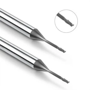
Graphite Cutting Temperature: How Does Cutting Temperature Affect Chip Formation?
In graphite electrode milling, thermal monitoring focuses on contact zone dynamics rather than part heat. During continuous production runs, initial parts yield uniform debris, but late-stage cycles often generate fine airborne dust and degraded surface textures. This shift involves friction build-up, heat transfer, and mechanical wear in the cutting zone. While less obvious than in titanium milling, graphite cutting temperature directly alters contact mechanics and edge stability.
Never treat thermal build-up as an isolated metric. Spindle speed, chip load, tool edge hone, friction coefficients, and dust evacuation airflow dictate heat generation and dissipation. When thermal equilibrium shifts, micro-fracture behavior and wear rates change rapidly. We evaluate process stability by correlating spindle acoustic signatures, debris morphology, flank wear, and part surface finish rather than relying on a standalone pyrometer reading.
The Generation Mechanism of Graphite Cutting Temperature
Heat generation in graphite milling originates from mechanical energy conversion during micro-fracture and continuous tool-substrate rubbing. Because graphite possesses high thermal conductivity, heat rapidly dissipates through the electrode bulk, tool shank, air blast, and evacuated particles. The localized graphite cutting temperature represents a dynamic equilibrium between continuous friction generation and multi-path heat dissipation.
As diamond coatings or carbide cutting edges wear down, rubbing friction outpaces clean brittle fracture. This feedback loop elevates temperatures and alters dust generation patterns during late-stage cycles. When thermal rise coincides with excessive fine dust and dull sidewalls, inspect cutting edge degradation and flute packing rather than merely turning up external air nozzles.
The Relationship Between Cutting Temperature and Brittle Graphite Machining
Unlike ductile metals that soften under elevated cutting temperatures, graphite retains its brittle fracture mode across normal machining ranges. Material removal depends on micro-crack initiation driven by mechanical loads, contact friction, and substrate grain density. In high-feed graphite brittle machining, thermal conditions act as an auxiliary factor that accelerates abrasive tool wear and alters localized friction fields.
When clean corner shearing turns into micro-chipping, evaluate cutting edge roundness and rubbing zones simultaneously. Thermal fluctuations matter primarily when coupled with spindle load spikes, chatter vibration, and erratic debris size. If edge retention and dust consistency remain stable under moderate heat, the process is sound; simultaneous degradation across indicators calls for an immediate feed or tooling adjustment.
The Relationship Between Graphite Cutting Temperature and Chip Formation
Thermal build-up influences debris morphology indirectly by shifting contact friction and accelerating edge hone degradation. As tool flutes wear, the cutting edge grinds rather than cleaves, pulverizing debris into fine dust while increasing frictional heat. Tracking graphite cutting temperature alongside chip evacuation provides an accurate gauge of whether material is fracturing cleanly or grinding against the tool.
Compare debris morphology between initial roughing passes and late-stage cycles to pinpoint process degradation. We log particle size distribution, sidewall finish, corner integrity, and flank wear simultaneously. If temperature spikes coincide with ultrafine powder surges and edge chipping, the cutting zone has shifted from controlled fracture to destructive friction rubbing.
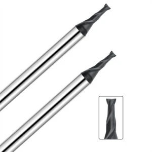
The Relationship Between Graphite Chip Formation and Graphite Tool Wear
Tool degradation in graphite milling occurs progressively across extended cycles rather than as sudden catastrophic failure. In high-volume electrode runs, initial parts maintain tight dimensional accuracy, but dust accumulation increases as the cutting edge slowly rounds. Evaluating these dynamics proves that graphite chip formation and edge life share an active feedback loop. Chip fracture patterns directly alter the mechanical contact environment at the tool edge.
When diagnosing rapid end mill wear, look beyond measuring standard flank wear lands. Inspect particle fracture uniformity, chip dwell time in the flutes, and high-frequency tool chatter. Highly abrasive graphite grains accelerate wear when trapped in the cut zone. Correlating particle fragmentation, evacuation dynamics, and cutting edge degradation provides the clearest diagnostic path.
How Does Graphite Chip Formation Affect Graphite Tool Wear?
Promptly evacuated fragments impact cutter life far differently than trapped micro-particulates. When cutting edges produce clean, crisp fractures, particles exit flutes instantly, keeping mechanical loads stable. Trapped dust recirculates between the tool flank and workpiece walls, causing intense micro-abrasion. For this reason, evaluating graphite tool wear requires analyzing chip fracture mechanics alongside flute evacuation efficiency.
If tool life is acceptable in shallow passes but degrades rapidly in deep slots, check for debris packing. Microscopic edge inspection before and after cycles reveals whether wear stems from substrate hardness or secondary particle grinding. A sudden shift toward ultrafine dust signals severe recirculation, turning stable cutting passes into abrasive erosion cycles.
Graphite Cutting Force and Graphite Tool Wear
Small-diameter end mills show extreme sensitivity to load shifts as micro-wear develops. As the cutting edge rounds, clean brittle shearing gives way to heavy mechanical rubbing, driving cutting resistance upward. Elevated loads trigger spindle vibration and corner micro-chipping, proving that graphite cutting force and tool breakdown directly amplify each other.
When wear accelerates unexpectedly, verify part clamping rigidity, dynamic tool runout, and programmed chip loads. Cutting forces that are too low cause the tool edge to burnish and rub rather than fracture the material. Maintaining consistent chip load ensures clean brittle fracture, protecting cutting edges from destructive friction and cyclical impact shocks.
How Graphite Chips and Dust Accelerate Tool Wear
Continuous electrode production frequently leads to heavy dust accumulation inside deep cavities. Un-evacuated graphite dust acts as a continuous abrasive lapping compound between the cutter clearance face and the finished wall. Controlling graphite tool wear requires preventing airborne dust and micro-chips from lingering inside the active cutting path.
When tools show broad flank wear lands, rounded hones, and dimensional drift without edge chipping, inspect chip extraction airflow. Enhancing vacuum extraction and directed air blasts stabilizes flank wear rates across long production runs. Clearing abrasive debris immediately delivers better tool life than lowering spindle speeds or running conservative feeds.
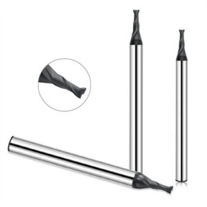
How Does Graphite Chip Formation Affect CNC Graphite Machining Quality?
Machining debris is not just shop-floor waste; it records the physical state of the cut zone. From tool engagement and load concentration to crack propagation, brittle fracture, and evacuation, every phase directly affects final part tolerances. In our machine shop, we evaluate debris morphology, cutting loads, tool geometry, thermal levels, and flank wear together. Monitoring stable graphite chip formation serves as the most dependable way to verify process control.
When troubleshooting surface roughness, edge chipping, or dimensional drift, compare debris characteristics before making program changes. Check whether roughing produces uniform fragments, finishing generates excessive dust, or chips turn irregular as tools wear. Rather than changing parameters at the first sign of trouble, analyze the links between graphite grain size, edge sharpness, cutting forces, and chip evacuation.
Graphite Chip Formation and Surface Finish
In precision electrode milling, surface defects leave clear warning signs in the evacuated debris. Stable material removal leaves uniform, clean toolpaths along sidewalls and pocket floors. When crack propagation becomes erratic or fine dust recirculates through the flutes, finished surfaces quickly develop pitting, micro-grooves, and cloudy textures. Stable graphite chip formation remains vital for maintaining tight surface roughness requirements.
If surface roughness spikes unexpectedly, compare chip morphology between the start and end of the cycle. Synchronized changes—such as debris turning into ultrafine dust while surface quality drops—point to flank wear, tool rubbing, and particle re-cutting. Inspect the cutting edge micro-geometry and vacuum suction volume before simply dropping the programmed feed rate.
Graphite Chip Type and Edge Chipping
Thin-walled ribs, deep slots, and sharp corners demand strict control over material fracture boundaries. When graphite fractures cleanly into uniform grains and clears the flutes instantly, part corners stay sharp. If cutting forces spike and cracks extend beyond the programmed cut path, severe micro-chipping occurs. Tracking every shift in graphite chip type prevents unexpected corner blowouts and scrap parts.
Pay close attention to debris behavior during tool lead-ins, cornering moves, and lead-outs on micro-features. When oversized chunks appear alongside edge breakout, inspect tool runout, stock transitions, and workholding rigidity before blaming material brittleness. Keeping crack propagation confined inside the cut envelope protects fragile electrode features and prevents costly rework.
Graphite Milling Mechanism and Machining Defects
Most graphite machining defects trace back to disruptions in the material removal process. Tool geometry dictates contact angles, cutting forces drive local stress fields, and grain structures guide crack propagation paths. Thermal build-up, flank wear, and poor dust extraction further destabilize the cut zone. Understanding the fundamental graphite milling mechanism keeps you from treating surface flaws, edge chipping, and tool wear as unrelated problems.
When diagnosing machining defects, work backward to determine what changed just before the issue started. Evaluate chip morphology, tool sharpness, spindle load, cut temperature, and clamping rigidity before modifying feed rates. Correlating part drawings, graphite grades, tool specs, and cutting parameters allows us to pinpoint whether the issue stems from brittle fracture mechanics, chip formation, or tool-workpiece dynamics.
FAQ: Graphite Chip Formation and Graphite Milling Mechanism
Most graphite electrode milling issues trace back to a few fundamental cutting mechanics that operators overlook on the shop floor. Questions often center on why graphite forms abrasive dust, why debris changes across grades, and why edge chipping coincides with tool wear. To resolve these issues, we synthesized the physics of brittle fracture, tool geometry, cutting loads, thermal build-up, and evacuation into this direct guide. Use these engineering answers to troubleshoot your setup by evaluating real-world chip morphology, surface finish, and tool edge wear.
How Does Chip Formation Occur in Graphite Milling?
Graphite chip formation follows a distinct mechanical sequence: cutting edge engagement, localized stress concentration, micro-crack initiation, crack propagation, and brittle detachment. Unlike ductile metals that form curled chips via continuous plastic shear, graphite shears via micro-fracture, releasing granular debris and fine dust. Stable milling requires keeping micro-crack propagation confined directly ahead of the active cutting edge.
Why Is Graphite Machining Considered Brittle Machining?
Graphite machining is classified as brittle machining because material removal occurs exclusively through brittle fracture rather than plastic deformation. As the cutting edge exerts compressive and shear loads, micro-cracks form along grain boundaries, binder interfaces, and internal pores. If cutting forces spike, these cracks propagate past the programmed cut boundary, causing severe edge chipping and pit marks.
What Are the Main Graphite Chip Types?
CNC graphite milling generates three primary debris categories: fine airborne dust, granular powder, and irregular, blocky fragments. Roughing passes with larger chip loads generate coarse fragments, whereas micro-tool finishing produces fine powder. Evaluating whether your chip type is optimal requires cross-referencing graphite grain size, edge hone condition, and workpiece wall integrity.
How Does Graphite End Mill Geometry Affect Chip Formation?
Cutting edge sharpness, rake angle, clearance relief, flute volume, and helix angle govern tool engagement dynamics and fracture boundaries. These geometric variables dictate how mechanical loads concentrate in the workpiece and how quickly abrasive debris clears the cutting zone. Proper tool geometry ensures uniform chip evacuation and prevents catastrophic edge breakout in thin-walled features.
How Does Graphite Cutting Force Affect Chip Formation?
Dynamic cutting forces directly regulate the depth and direction of micro-crack propagation within the graphite matrix. Excessive tool loads or dynamic runout drive fractures deep into the workpiece substrate, shifting fine granular debris into oversized, irregular chunks. Monitoring spindle load and cutting acoustics helps detect force spikes before they trigger edge breakout.
Does Graphite Cutting Temperature Affect Chip Formation?
While mechanical force dominates brittle fracture, cutting zone temperature serves as a critical indicator of friction build-up and tool wear. High temperatures indicate that dull flutes are grinding and rubbing against the workpiece rather than cleaving clean chips. A thermal spike paired with excessive fine dust confirms that the process has shifted from brittle fracture to abrasive rubbing.
How Does Chip Formation Affect Graphite Tool Wear?
Debris morphology and cutter life share a direct mechanical feedback loop during graphite milling. Cleanly fractured particles that evacuate immediately cause minimal abrasive wear on diamond-coated flutes. When fine dust lingers in the cavity, it recirculates between the tool relief face and the finished wall, acting as a grinding compound that accelerates flank wear.
Why Does Graphite Produce Fine Chips During Milling?
Graphite generates fine particulate during light finishing passes because micro-cracks propagate over extremely short distances before reaching a free surface. This micro-cleavage releases individual carbon grains as fine dust rather than cohesive chips. If excessive dust appears during roughing, inspect edge dulling, tool rubbing, and chip re-cutting immediately.






