



We once consulted on a challenging project involving precision graphite electrodes. The client assumed that flooding the cut with traditional cutting fluids would control thermal buildup and tool wear. Instead, the results were disastrous: rapid abrasive tool wear, micro-chipping along the cutting edges, and unpredictable tool life across identical workpieces.
Years of hands-on CNC experience have taught us that the fundamental logic of machining graphite is entirely different from cutting metals. Coolant strategies designed for steel or aluminum fail here because graphite behaves differently under load. When paired with high-volume vacuum systems, dry graphite machining consistently produces superior dimensional accuracy and edge retention.
Graphite machining does not produce continuous chips. Because graphite is inherently brittle, material removal occurs via localized brittle fracture and micro-cracking rather than plastic deformation. As the cutter engages the workpiece, the material micro-fractures into extremely fine, abrasive particles rather than drawing heat away in long chips.
When cutting fluid mixes with these fine particles, it creates a heavy abrasive slurry. This slurry acts like lapping compound, grinding away cutting edges and accelerating tool wear. Running the process dry allows high-velocity air and dust collection systems to evacuate particles instantly before they re-enter the cut zone.
Graphite generates localized friction heat, but it dissipates thermal energy rapidly without melting or adhering to the flute. Consequently, graphite end mill wear is driven almost entirely by mechanical abrasion rather than thermal softening. Relying on diamond-coated graphite end mills and optimized feed rates is far more effective than introducing fluid.
Achieving repeatable tolerances requires balancing edge geometry with aggressive particle evacuation. By eliminating coolant, shops avoid messy sludge management, protect sensitive machine ways from conductive dust paste, and significantly extend graphite end mill tool life. Dry cutting is not a compromise—it is the engineered standard for precision graphite components.
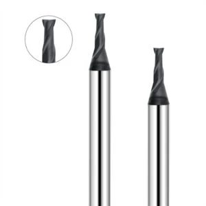
Dry Graphite Machining: Why Is Graphite Suited for Dry Cutting?
Machining precision graphite electrodes behaves very differently from cutting steel. Introducing cutting fluid does not improve cycle stability; instead, it creates a messy conductive sludge inside the machine enclosure. In our production facility, dry graphite machining works because material removal, thermal dissipation, and vacuum extraction work together naturally without liquid interference.
At tool engagement, graphite micro-fractures instead of forming continuous ductile ribbons. Its porous structure and low fracture toughness cause immediate particle detachment along grain boundaries. Pairing sharp tool edges with high-flow dust extraction stabilizes the cut, eliminates edge chipping, and delivers far more consistent tool life than flood coolant.
Graphite Machining Mechanism: The Nature of Brittle Cutting in Graphite
Grain size and bulk density directly dictate cutting behavior across different graphite grades. The graphite machining mechanism relies on localized mechanical shear that triggers controlled micro-cracking rather than plastic deformation. As cutting loads build at the tool edge, stress concentrations release clean fractures, generating fine granular dust instead of curled metal chips.
Maintaining structural edge stability requires strict control over cutting forces and tool edge geometry. Even minor tool flank wear transforms clean shearing action into blunt crushing impacts, resulting in severe workpiece breakout. Tracking surface finish and particle size helps us catch edge degradation early, preserving process stability during long CNC cycles.
Graphite Brittle Machining: How Brittle Fracture Forms Chips
Clients often misdiagnose high dust volume as a chip-evacuation failure, but it is normal material behavior. In graphite brittle machining, material detachment occurs via micro-crack propagation and grain dislodgement. You will never observe the continuous chip flow typical of aluminum or stainless steel during this process.
Pushing feed rates too aggressively increases cutting pressures and causes uncontrolled localized breakout. Machinists must tune depths of cut and spindle speeds to control precisely where the material fractures. Managing brittle fracture mechanics yields clean corner retention on delicate electrode ribs, which matters far more than raw volumetric removal rates.
Graphite Machining Without Coolant: Why Coolant Is Usually Unnecessary
Metalworking fluids exist primarily to lubricate tool-chip interfaces and absorb continuous cutting heat. However, graphite machining without coolant is ideal because graphite dissipates thermal energy rapidly without melting or adhering to the tool flutes. Cutting fluid only turns airborne dust into an abrasive paste that rapidly erodes tool coatings.
Running dry protects critical CNC hardware, keeping conductive residue from fouling machine way covers and linear guides. With dedicated high-velocity vacuum hoods and diamond-coated tooling, dry cutting delivers cleaner parts and repeatable tolerances. Success relies entirely on evacuating fractured particles at the source rather than flushing them with fluid.
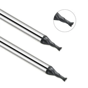
Graphite Brittle Machining: Fracture and Chip Formation in Dry Cutting
Expanding your machining pass on graphite electrodes produces a noticeable surge of fine dust. This volume increase is not necessarily an extraction failure, but an inherent trait of graphite brittle machining. Material removal happens through localized stress concentrations, crack propagation, and grain dislodgement rather than plastic chip shearing.
We treat precision graphite milling as a process of controlled fracture. If depth of cut or feed per tooth is too aggressive, cutting stresses spike and push cracks beyond the intended shear zone. Controlling these fracture boundaries ensures sharp corner retention and lets high-flow vacuum systems clear detached particles instantly.
The Relationship Between Graphite Brittle Fracture and Cutting Force
Balancing cutting loads requires linking spindle speed, feed rate, and tool geometry to the material’s grain boundaries. When an end mill engages, cutting force concentrates into a tiny contact patch, initiating micro-fractures. Because graphite brittle fracture is non-linear, momentary localized stress spikes matter far more than average cutting force readings.
In complex electrode details like thin ribs and narrow slots, sudden tool engagement spikes edge chipping. Ramping spindle speed blindly rarely solves corner breakout. Instead, reducing stepover and optimizing corner deceleration stabilizes cutting loads, maintaining crisp structural edges without burning through tooling.
Graphite Chip Formation: How Graphite Particles Detach from the Machining Zone
Unlike continuous metal ribbons, graphite chips are tiny granular fragments. As the tool flute applies pressure, micro-cracks travel across grain boundaries until small particles detach. This graphite chip formation relies purely on mechanical fracturing, requiring high-velocity airflow to sweep the detached dust out of the cut zone immediately.
Secondary rubbing occurs when detached graphite particles re-enter the cut path before vacuum extraction catches them. These loose granules act like loose abrasives, dulling cutting edges and scuffing delicate surface finishes. Stable directional air nozzles pointed directly at the tool-workpiece interface prevent this regrinding and protect tool coatings.
Graphite Machining Dust: Why Dry Machining Generates Large Amounts of Graphite Dust
High spindle speeds and shallow cuts naturally produce micro-fractured particles that suspend in air. Generating high volumes of graphite machining dust is an inevitable byproduct of running dry. Rather than attempting to suppress it with wet coolants, production shops must focus on capturing dust directly at the generation point.
Poor extraction usually stems from turbulent spindle downdrafts scattering particles, not weak vacuum suction alone. Enclosing the spindle area with a custom capture shroud matches extraction airflow to cutter rotation. Sealing the work envelope and positioning vacuum nozzles within inches of the tool keeps precision ways clean and operators safe.
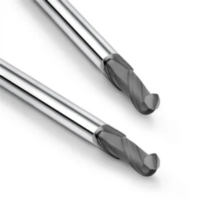
Graphite Cutting Heat: Generation and Transfer in Dry Machining
Running without coolant does not automatically trigger thermal damage on your workpiece or cutters. In stable dry graphite machining, heat develops constantly, but the process stays balanced if chip evacuation and cutting loads are dialed in. Our shop evaluates heat transfer paths and thermal dissipation rates rather than simply assuming that high cutting temperatures are destroying the tool.
Friction, micro-fracture resistance, and energy conversion drive graphite cutting heat during dry milling. If a tool loses its edge prematurely on precision electrodes, the cause is rarely heat buildup alone. Instead, we inspect tool runout, dust re-cutting, and chip clearance; heat is typically an operational symptom rather than the primary driver of tool failure.
Primary Sources of Graphite Cutting Heat
Tool-workpiece contact friction generates the vast majority of cutting zone thermal energy. A sharp cutting edge initiates clean fracture lines, directing mechanical energy into particle separation rather than heat. When edges dull, shearing collapses into blunt rubbing and compression, causing spindle load, localized heat generation, and audible cutting chatter to spike simultaneously.
Tool runout and poor toolholder rigidity also multiply friction by creating erratic tooth engagement. This uneven loading traps detached dust against the workpiece, transforming cutting action into abrasive grinding. Before slowing your spindle down to reduce heat, verify edge sharpness, runout under 0.0001″, and consistent chip evacuation across the tool flutes.
How Graphite Thermal Conductivity Affects Cutting Heat
Graphite thermal conductivity varies significantly across different bulk densities and grain sizes. Premium isotropic grades dissipate heat quickly into the bulk stock, whereas porous extruded grades trap energy near the surface. Because of this variation, identical feeds and speeds produce entirely different thermal loads across different workpiece materials.
Finishing cuts require close monitoring of thermal expansion and flute friction. If tool flank wear accelerates while the electrode stays cool, friction heat is concentrating at the tool edge. Never copy feeds across differing grain grades blindly; re-verify tool contact time and thermal response whenever you switch graphite stock.
How Cutting Heat Affects the Dry Graphite Machining Process
Controlled cutting heat rarely triggers dimensional errors or tool breakdown on its own. Problems arise during long, uninterrupted dry graphite machining cycles when thermal friction pairs with dust re-circulation. This combination erodes tool coatings, weakens cutting edge geometry, and causes dimensional drift across tight-tolerance electrode features.
Process optimization means auditing the complete machining cycle instead of checking temperature at a single moment. Maintain steady vacuum airflow and stable chip evacuation to prevent abrasive dust from trapping thermal energy. If friction surges, adjust flute geometries and depths of cut rather than just reducing spindle RPM.
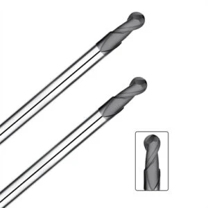
Graphite Machining Dust: Why Controlling Dust is Essential in Dry Machining
Airborne dust is the most underestimated hazard when machining graphite electrodes. Operators often fixate on surface finishes and cycle times, treating dust purely as an end-of-shift cleaning chore. However, spindle rotation and rapid traverse moves propel micron-sized conductive particles directly into machine cavities, threatening guideways and sensitive electrical enclosures.
Evaluating a dry graphite machining cell requires analyzing the entire path from particle generation to filtration. High CFM ratings on paper mean nothing if turbulent air scatters particles away from the intake hood. Reliable production demands integrating graphite machining dust control directly into the setup rather than relying on standard shop vacuums.
How Graphite Machining Dust Affects CNC Machining Systems
Uncontrolled dust infiltration directly compromises CNC machine repeatability. Over continuous production runs, microscopic graphite particles bypass standard way wipers, mixing with axis lubricants to form a grinding compound. This abrasive paste wears out linear guideways and ball screws, inducing mechanical backlash and dimensional drift on precision electrode contours.
When positioning accuracy degrades or axis drives draw excess current, inspect your enclosure sealing before blaming mechanical wear. Ensure negative air pressure isolates the cutting envelope, and position high-velocity intake nozzles adjacent to the spindle nose. Containing dust at the cut prevents contamination of critical mechanical components and cuts preventive maintenance downtime in half.
How Graphite Dust Accelerates Graphite End Mill Wear
Premature edge failure often stems from regrinding detached particles rather than the cut itself. When microscopic debris is not evacuated instantly, it gets trapped between the relief face and the workpiece. This secondary rubbing acts like lapping paste, stripping protective diamond layers and accelerating graphite end mill wear.
Tool coatings and flute geometry determine how well a cutter handles localized abrasion. Uncoated carbide tools dull almost instantly, whereas high-density diamond coatings provide the hardness needed to withstand continuous particle rubbing. If tool life drops unexpectedly, optimize vacuum airflow to clear the cut zone before throttling your feed rate.
Why Dust Extraction is Key to Dry Graphite Machining
Because brittle fracture always creates fine particles, the objective is never zero dust generation. Instead, success hinges on whether your dust collection captures debris the millisecond it breaks free from the stock. Point-of-generation extraction prevents dust clouds from expanding inside the work envelope and migrating into the plant atmosphere.
Effective extraction must synchronize with spindle rotation and programmed cutter paths. Adjustable vacuum shrouds that follow the Z-axis ensure intake nozzles remain within inches of the cutting zone without restricting tool changes. Pairing balanced airflow dynamics with high-efficiency filtration creates a stable dry graphite machining process that protects machines and extends tool life.

Graphite End Mill Wear: How Dry Machining Affects Tool Wear
Counting completed workpieces is an unreliable way to track cutting edge longevity. An end mill might hold tight tolerances on the first few electrodes, only to suffer rapid flank wear, edge rounding, and micro-chipping as cutting hours accumulate. In production environments, graphite end mill wear results from a combination of grain abrasive action, cutting forces, and ambient dust management.
Grain density and material porosity directly govern how aggressively a workpiece abrades the cutting edge. Inspecting tool flanks alongside dust evacuation efficiency catches edge breakdown before parts fail dimensional quality checks. In stable dry graphite machining, pinpointing the exact transition from steady cutting to severe mechanical friction prevents costly electrode scrap.
Primary Wear Mechanisms of Graphite End Mills
Catastrophic tool breakage is rare when milling graphite; progressive abrasive wear along the tool flank is the real threat. Hard microscopic particles in the workpiece material constantly rub against the carbide substrate, eroding edge geometry and dulling the tool. Flank face abrasion and micro-chipping indicate that mechanical wear is overtaking clean fracture.
Cutting edge geometry dictates how long an end mill holds true. Sharp positive rakes cleanly initiate micro-fracturing, while worn, rounded edges exert high compressive loads that trigger electrode breakout. On complex graphite electrode ribs, indexing or replacing the cutter before edge degradation accelerates prevents secondary damage to delicate part features.
Why Graphite End Mill Tool Life Is Affected by Dust
Dust that lingers in the cutting envelope directly degrades the tool edge. When detached particles re-enter the flute contact zone, they act as an abrasive lapping medium against the relief face. This triggers a destructive cycle of friction and heat, shortening graphite end mill tool life far faster than continuous cutting in clean air.
Identical cutting tools on identical machine programs often show radically different operational lifespans. In almost every case, the underperforming machine suffers from poor suction velocity or turbulent airflow that traps dust around the tool tip. Before paying for costlier cutting tools, optimize your vacuum nozzle positioning to eliminate dust recutting at the source.
How Diamond Coated Graphite End Mills Improve Wear Resistance
Extended, high-volume machining programs demand diamond coated graphite end mills to resist continuous mechanical abrasion. Graphite quickly rubs uncoated carbide down to a dull radius, whereas chemical vapor deposition diamond layers provide extreme surface hardness. This engineered diamond barrier protects the edge profile, maintaining dimensional accuracy across long finishing passes.
A premium coating cannot overcome severe mechanical runout, spindle vibration, or inadequate vacuum extraction. If cutting tools run out more than 0.0001″ or loose dust constantly grinds against the flutes, diamond films can peel or micro-chip under shock. Treating diamond tooling as part of a rigid setup—alongside balanced toolholders and dedicated dust collection—unlocks maximum tool life.
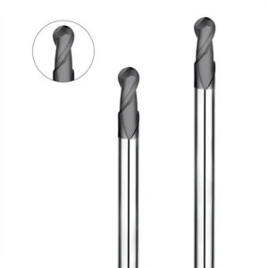
Graphite Machining Without Coolant: Why Coolant Isn’t Always Better
When cutting temperatures rise during electrode fabrication, machinists often reach instinctively for the coolant valve. Yet flooding the cut rarely solves premature tool wear, runout errors, or edge breakout. Opting for graphite machining without coolant is not just a shop preference; it is an engineered strategy based on brittle fracture dynamics and fast particle evacuation.
Coolant selection should prioritize system reliability over conventional metalworking habits. Running dry allows high-velocity vacuum hoods to pull abrasive dust out of the envelope before particles recirculate. When balanced against tool paths, spindle speeds, and chip extraction, dry processing consistently delivers cleaner, more repeatable production runs.
Differences Between Graphite Machining with Coolant and Dry Graphite Machining
Metalworking fluids flush stringy chips, lubricate shear zones, and absorb heat during plastic deformation. However, graphite machining with coolant behaves poorly because fractured graphite creates fine powders rather than continuous ribbons. Coolant streams cannot suspend these dense particles cleanly, turning the cutting zone into a recirculating basin of abrasive grit.
In contrast, dry graphite machining relies on directional airflow and negative pressure to clear fractured particles instantly. Machinists maintain thermal stability by tuning feed per tooth, radial engagement, and spindle speeds rather than pumping liquid. Removing fluid variables leaves the cut zone visible, stable, and much easier to optimize for tight tolerances.
How Coolant Affects Graphite Dust, Tools, and the Machine Environment
Introducing cutting fluids turns dry particulate into a thick, conductive sludge. In graphite machining with coolant, this paste cakes onto fixtures, clogs sump filters, and coats machine way covers. Cleaning this abrasive mess requires extensive manual labor, and the slurry often bypasses wipers to score precision ground ball screws.
Fluid presence also damages cutting tool edges. Instead of floating away, microscopic graphite particles remain trapped in the liquid film between the tool relief face and the workpiece. This constant fluid-borne slurry laps away sharp edges, strips protective diamond coatings, and accelerates flank wear far faster than clean air cutting.
When Graphite Machining Without Coolant Is More Suitable
Standard electrode fabrication, EDM tooling, and precision mold cores are ideal candidates for graphite machining without coolant. These parts require crisp edge retention and sharp ribs that brittle fracture can easily destroy under hydraulic fluid pressure. Running dry with high-suction hoods evacuates dust immediately, ensuring micro-fractures stay cleanly contained within the programmed cut geometry.
Wet milling should be reserved only for legacy shops lacking dedicated negative-pressure dust collectors. Before locking in a production method, benchmark tool wear, surface finishes, and machine cleanup overhead across a test batch. Running dry preserves machine accuracy, lowers tooling costs, and delivers the long-term process control modern CNC shops demand.
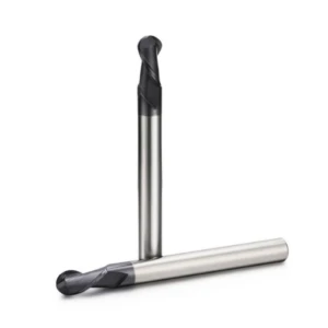
Dry Graphite Machining System: How to Establish a Stable Dry Machining System
Achieving repeatable tolerances in graphite milling requires treating the entire cell as an integrated dry graphite machining system. Material micro-fracturing, cutting forces, thermal dissipation, and dust collection operate in continuous synergy. Adjusting speeds and feeds in isolation will never solve premature edge wear if ambient dust constantly recirculates across the toolpath.
When identical CNC programs yield inconsistent electrode finishes, audit structural machine rigidity, tool runout, and negative enclosure pressure before modifying toolpaths. Mechanical vibration combined with trapped particulate turns controlled shearing into uncontrolled edge chipping. Isolating these operational variables methodically stabilizes long production cycles.
Configuring the Graphite Dust Extraction System
Point-of-generation capture defines the efficiency of any graphite dust extraction system. Microscopic particles must be evacuated the instant they break free from the workpiece matrix. Allowing dust clouds to expand inside the machine enclosure before relying on bulk filtration overburdens filters and compromises linear way covers.
Position adjustable vacuum nozzles within two inches of the tool flutes to capture particles directly along their natural tangential throw. If visible dust clouds linger around the spindle nose, realign intake ducting and check filter backpressure before cranking blower motor RPM. Stable negative pressure keeps conductive dust out of critical CNC ball screws.
Matching Graphite End Mills with Dry Machining
Selecting graphite end mills requires evaluating substrate grade, flute relief angles, and coating hardness against the specific workpiece grain size. High-density diamond coatings provide the abrasive resistance needed to prevent premature flank wear in dry environments. However, excessive tool overhang or runout exceeding 0.0001″ will cause brittle diamond films to micro-chip immediately.
Roughing stages demand high-rigidity cutters that support efficient particle fracture, while finishing passes rely on ultra-sharp edge prep to preserve delicate electrode ribs. We match cutter geometry directly to material grain structure, bulk density, and programmed stepovers. Selecting the proper tool substrate ensures clean brittle fractures without creating secondary workpiece breakout.
Coordinating Machining Parameters, Machine Rigidity, and Dust Control
Optimizing dry milling parameters requires balancing spindle RPM, chip load per tooth, and machine dynamics as a single workflow. Excessive depth of cut spikes localized cutting forces, transforming micro-shearing into aggressive material blowouts. Proper dynamic parameter tuning keeps fracture zones small, predictable, and aligned with machine rigidity.
When qualifying new graphite grades, adjust only one variable at a time while inspecting edge breakout under magnification. Track the relationship between feed rates, dust particle size, and spindle vibration to isolate mechanical limits. Dialing in this balance guarantees maximum tool life, crisp part definition, and dependable dry machining performance.
FAQ: Dry Graphite Machining and the Graphite Dry Cutting Mechanism
Evaluating a graphite machining setup requires looking past conventional metalworking practices. In actual shop environments, process consistency hinges on how effectively your parameters accommodate brittle material fracture, localized thermal dissipation, and airborne particle dynamics.
These practical FAQs address real-world machining challenges observed across thousands of electrode runs. Understanding how dust evacuation, tool wear mechanisms, and dry cutting interact helps machinists stabilize part tolerances and maximize equipment uptime.
Why Does Graphite Machining Work Better Without Coolant?
Graphite separates via micro-fracture rather than plastic shearing, producing fine granular dust instead of curled metal ribbons. Introducing cutting fluid does not improve shearing; it merely turns dry particulate into an abrasive slurry that laps away cutting edges and cakes machine interiors.
Adopting graphite machining without coolant keeps the work area clean and prevents conductive sludge from penetrating machine ways. When combined with localized vacuum hoods, dry cutting allows detached particles to evacuate immediately, stabilizing cycle times and preserving dimensional accuracy.
Does Dry Machining Increase Graphite Cutting Heat?
Dry cutting does not inherently cause destructive thermal spikes. Because graphite exhibits favorable thermal conductivity and brittle fracture absorbs little plastic deformation energy, localized graphite cutting heat dissipates rapidly into the evacuated air stream.
Thermal problems almost always stem from dull tooling, excessive runout, or dragging relief faces rather than the lack of fluid. Verifying sharp edge prep and proper chip loads controls frictional rubbing far more effectively than pouring coolant over the cut zone.
Does Graphite Machining Dust Reduce Graphite End Mill Tool Life?
Recirculating dust severely degrades cutting edges through secondary abrasion. When detached particles fail to clear the cutting envelope, they get pulled between the tool relief face and the workpiece, acting like lapping compound that strips protective coatings.
Consequently, unmanaged graphite machining dust directly shortens usable graphite end mill tool life. Setting up high-velocity vacuum nozzles at the spindle nose prevents this regrinding cycle, keeping flank wear predictable across extended electrode cycles.
Is a Diamond-Coated Graphite End Mill Better for Dry Machining?
Extended dry runs require diamond-coated graphite end mills to withstand the severe abrasive action of fine-grain graphite. Chemical vapor deposition diamond layers provide extreme hardness that resists edge rounding far longer than uncoated solid carbide.
However, diamond films cannot survive toolholder runout over 0.0001″ or severe machine chatter. Tool rigidity, proper rake angles, and dialed-in feeds must accompany diamond tooling to achieve maximum wear resistance without chipping the ultra-hard coating.
How Can Graphite Dust Extraction Improve Dry Graphite Machining?
A dedicated graphite dust extraction system stabilizes dry milling by clearing fractured particles the millisecond they break free. Evacuating dust at the generation point stops abrasive particles from circulating inside the enclosure and settling into mechanical drive systems.
Effective extraction requires placing capture nozzles within inches of the tool flutes, directly in the path of the cutter’s tangential throw. Maintaining stable negative pressure protects linear guideways, keeps finishes consistent, and ensures reliable dry graphite machining performance.






