


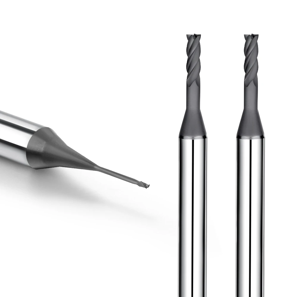
A client recently approached our shop with a frustrating graphite electrode milling failure. Their CNC program produced clean results on the first few parts, but edge chipping quickly escalated, fine dust spiked, dimensional tolerances drifted, and surface finishes deteriorated. What baffled them most was that they were already running carbide cutting tools within standard machining feeds and speeds.
In our decades of CNC electrode production, we see this scenario constantly. Premature tool failure rarely stems from a “bad tool.” Instead, it indicates a fundamental mismatch between the tool’s cutting edge geometry, substrate, coating, and the destructive micro-fracture mechanism unique to graphite.
Graphite machining does not produce continuous chips through plastic deformation like conventional aluminum or steel cutting. When a graphite end mill enters the workpiece, the material undergoes brittle fracture, micro-cracking, and abrasive particle shedding. This cutting mechanism directly dictates tool deflection, cutting forces, airborne graphite dust, corner chipping, and edge wear.
Because of this abrasive dynamic, selecting the best graphite end mills requires looking far beyond tool diameter and unit price. Experienced machinists assess graphite grade, grain size, shore hardness, and roughing versus finishing allowances. These material variables dictate whether your tool requires razor-sharp edge preparation, reinforced flute core rigidity, or specialized relief angles.
For high-density, highly abrasive electrode materials, we prioritize diamond-coated graphite end mills. A genuine diamond coating delivers the extreme surface hardness required to resist severe abrasive wear. However, for short-run prototypes or budget-constrained cycles, high-grade uncoated carbide end mills or DLC-coated options may offer a more economical balance.
Tool geometry must also be matched to structural rigidity and part features. In the ongoing debate between 2-flute vs. 4-flute graphite end mills, neither configuration is universally superior. A 2-flute design maximizes flute clearance for bulk material evacuation, whereas a 4-flute tool enhances core strength and perimeter finish when chip packing is managed correctly.
Once production scales from initial prototyping to high-volume runs, process stability becomes the primary performance metric. Optimized graphite end mill speeds and feeds, high-pressure vacuum extraction, and air-blast cooling directly govern actual tool life and repeatable tolerances. Applying metal-cutting principles to porous graphite almost always triggers rapid corner breakdown and scrapped electrodes.
True efficiency comes down to managing the physical interaction between the tool’s cutting edge and the graphite matrix. The so-called “best end mill for graphite machining” is never a one-size-fits-all product. It is the precise synergy of micro-grain substrate, coating adhesion, flute core geometry, and stable cutting parameters dialed in for your specific electrode grade.
To achieve consistent surface finishes and long tool life, operators must control cutting forces, grain fracture propagation, dust evacuation, and localized edge wear. Knowing how different tool profiles handle this brittle fracture zone is essential to high-speed graphite milling. Here is how a properly matched tool cuts cleanly through graphite instead of crushing it.

Graphite End Mill Cutting Mechanism: The Tool-Material Interaction
When milling graphite electrodes, initial tool entry often looks clean, but surface fragmentation changes drastically as cut depth, stepover, or feed direction shift. Rather than just watching the tool bite into the stock, we monitor contact zone stresses, material shedding mechanisms, airborne dust levels, and final edge integrity. Mastering the graphite end mill cutting mechanism means ensuring your tool systematically cleaves the graphite matrix rather than crushing it through uncontrolled fracturing.
Different graphite grades feature distinct grain sizes, Shore hardness values, and porosity levels, meaning identical machining setups will yield wildly divergent results. In our CNC shop, we first evaluate the material’s brittleness and abrasive rating, then balance tool diameter, flute geometry, and feed rate accordingly. This meticulous tuning ensures stable tool-workpiece contact, smooth chip evacuation, and minimal edge breakdown to maximize tool life.
How Graphite End Mills Remove Material During CNC Graphite Machining
Milling a graphite electrode cavity is far from standard metal shearing. As the cutting edge contacts the carbon matrix, it exerts concentrated compressive stress that fractures internal grain boundaries and micro-pores. Because graphite lacks metallurgical ductility, it cannot form continuous chips; instead, the tool continuously drives micro-fractures, releasing granular debris and fine carbon dust.
This brittle detachment dynamic is especially sensitive when cutting fine ribs or thin-walled electrodes. High cutting loads quickly shift clean shear action into aggressive grain breakouts, severely chipping delicate corners. Instead of instantly jumping to pricier cutters, we fine-tune edge sharpness, radial stepover, and chip load to guarantee each flute cuts predictably without fracturing thin walls.
Graphite Cutting Force, Brittle Fracture, and Chip Formation
Machining stability relies heavily on mitigating sharp cutting force spikes. Although graphite cuts with lower average spindle loads than steel, instantaneous cutting forces swing erratically depending on grain size, structural density, edge wear, and varying chip thickness. Sudden load spikes immediately trigger workpiece chipping, part breakout, and rough surface finishes across critical electrode features.
In actual production runs, brittle fracture propagation and chip clearance go hand in hand. Because graphite chips fracture along weak grain boundaries, airborne dust surges or pitch changes in the cut signify unstable material failure. We immediately optimize feed rates, tool path directions, and vacuum air blasts to ensure uniform chip evacuation and prevent turbulent fracturing inside the cut.
Impact of the Graphite End Mill Cutting Edge on Machining Quality
Part quality depends heavily on the microscopic condition of the graphite end mill cutting edge. A fresh, properly honed edge shears graphite cleanly, but micro-chipping instantly alters the tool’s contact geometry, turning clean shearing into destructive crushing. This contact change degrades surface Ra finishes and ruins crisp electrode corners during precision finishing passes.
To counter rapid abrasive wear, we balance razor sharpness with edge prep, optimized relief angles, and minimal spindle runout. An overly sharp, fragile edge chips instantly, while a blunt edge plows material, spiking dust and gouging floor finishes. A properly reinforced cutting edge stays sharp longer, cuts cleanly, and holds tight tolerances throughout demanding batch production runs.
Key Design Factors for Optimal Graphite End Mills: How Tool Geometry Affects Cutting Performance
In our CNC electrode shop, we often see jobs falter even when running premium carbide grades. Reviewing setup logs usually reveals that the failure stems from a geometric mismatch rather than a poor tool substrate. Roughing requires wide chip valleys for rapid dust evacuation, while finishing demands rigid edge geometry to protect part tolerances. Assuming more flutes and harder materials guarantee success is a fast track to broken tooling.
Selecting the best graphite end mills requires analyzing tool geometry as an interconnected system. Because graphite is extremely brittle and abrasive, a cutter must combine high edge toughness with reliable dust clearance. We match tool core thickness, relief angles, and flute spacing to the specific electrode density, feature depth, and programmed chip load.
2-Flute vs 4-Flute Graphite End Mills
For heavy roughing passes, we generally specify tools with fewer flutes to maximize clearance. Deeper chip pockets prevent packing when pocketing deep cavities or milling porous, high-wear electrode blocks. However, a low flute count struggles during delicate contouring, where wide tooth spacing and uneven tool engagement can leave coarse chatter marks across critical mold surfaces.
Deciding between 2-flute vs 4-flute graphite end mills depends entirely on the operation. A 2-flute cutter provides the open flute volume needed for aggressive roughing and high material removal rates without clogging. A 4-flute configuration increases core rigidity and lowers chip load per tooth, delivering the stable deflection resistance required for precision finishing and thin-rib detailing.
Graphite End Mill Flute Geometry and Chip Evacuation
Proper flute clearance is vital when managing graphite cutting dynamics. Unlike continuous metal curls, graphite shears into abrasive micro-granules and dry dust. If flute valleys are too shallow, airborne fines re-enter the cut zone, causing secondary rub that rapidly erodes the cutting edge. Graphite end mill flute geometry directly governs heat dissipation, edge life, and cut consistency.
We continuously optimize flute depth, core taper, and helix angles alongside active air-blast extraction. In deep slots, trapped powder acts like a grinding paste, creating uneven wall gouges and accelerated corner wear. If tool wear spikes during deep-pocket entry, clearing the evacuation path is far more effective than simply bumping up spindle RPM.
Cutting Characteristics of Small-Diameter Graphite End Mills
Micro-machining narrow electrode ribs and intricate details demands extreme caution. As cutter diameters shrink below 1 mm, shank rigidity drops exponentially, drastically reducing the edge load the tool can sustain. In high-detail jobs, roughing may run smoothly, but tiny finishing tools will snap instantly if programmed with standard proportional chip loads.
When deploying small-diameter graphite end mills, we recalibrate feed per tooth, stepover, and tool stick-out. Tool deflection and micro-chipping quickly ruin fragile electrode corners and destroy tight EDM tolerances. To maintain reliable tool life, we run ultra-short tool overhangs, verify sub-micron spindle runout, and prioritize consistent, light passes over aggressive cycle times.
Carbide Graphite End Mill vs. Uncoated Graphite End Mill: How Tool Material Affects Cutting
Many machine shops assume switching to a harder tool material automatically guarantees longer tool life and cleaner parts. In reality, successful milling depends on balancing substrate grain, graphite density, part tolerances, and cutting loads. Graphite may feel soft compared to steel, but its abrasive micro-particles create continuous flank friction that quickly dulls unsuited cutting edges.
Choosing between carbide graphite end mills and uncoated graphite end mills comes down to matching substrate properties to your batch size. Low-density prototype electrodes require vastly different edge geometry than high-density production runs. Substrate toughness, cobalt binder ratios, and edge preparation directly determine whether a cutter resists micro-chipping or prematurely destroys the electrode.
Cutting Performance of Carbide Graphite End Mills
Solid micro-grain carbide remains the standard foundation for high-performance electrode milling. Rather than chasing raw Rockwell hardness, experienced CNC machinists prioritize carbide wear resistance, transverse rupture strength, and cutting edge stability. When milling dense electrode blocks, a balanced carbide graphite end mill maintains edge geometry, preventing cutting force spikes and aggressive graphite dust generation.
Not every generic carbide cutter performs reliably in abrasive carbon environments. We evaluate tungsten carbide grain sizing, cobalt binder percentages, and edge hone radii before putting a tool in the spindle. A substrate that is too soft wears down within minutes, while an overly brittle edge fractures during chip load variations, driving up tool wear.
Suitable Conditions for Uncoated Graphite End Mills
Running uncoated graphite end mills makes strategic sense for rapid prototyping, one-off electrodes, and short production runs. Without a coating layer rounding the cutting edge, an uncoated tool delivers an extremely sharp, precise edge radius. This razor-sharp geometry cuts cleanly in low-density graphite with minimal cutting pressure, making it ideal for non-critical EDM jobs.
However, uncoated carbide cannot survive the severe abrasion of high-density production runs. Continuous contact with abrasive graphite dust quickly rounds the cutting edge, accelerating flank wear, causing dimensional drift, and leaving rough surface finishes. In long production cycles, the frequent tool offsets and tool changes of uncoated cutters quickly erase any initial cost savings.
Selecting the Right Substrate for Graphite Machining
Before choosing coatings or flutes, we evaluate graphite grade, grain classification, and feature geometries. High-density, fine-grain blocks require high-wear substrates with reinforced core rigidity, while micro-ribs and thin walls demand extreme edge toughness to prevent deflection. The right base tool material must match the mechanical stresses generated by your specific cutting path.
When evaluating the best end mill for graphite machining, we balance batch volume, surface roughness specs, and tool life targets. A standard micro-grain carbide substrate often handles standard runs, while severe production demands warrant geometry adjustments and diamond coatings. Choosing the right substrate ensures consistent dimensional accuracy across every electrode without overpaying for unnecessary tooling.
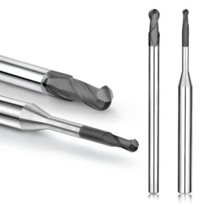
Diamond Coated Graphite End Mills: How Diamond Coatings Transform Graphite Machining Mechanics
In high-volume graphite electrode runs, we frequently see a predictable failure pattern. Initial cuts hold crisp edges, but abrasive graphite dust quickly erodes the tool flank, sparking micro-chipping across sharp electrode corners. This wear cycle accelerates rapidly in high-density, fine-grain graphite blocks. The root cause is rarely incorrect CAM programming, but rather severe abrasive erosion grinding away the cutting edge.
For uninterrupted production schedules, we consistently deploy diamond coated graphite end mills. A genuine diamond coating does far more than boost tool hardness; it creates an ultra-slick, wear-resistant shield over the carbide substrate. This protective barrier preserves original edge geometry despite constant exposure to abrasive carbon dust, ensuring long-term process stability.
How Diamond Coated Graphite End Mills Mitigate Abrasive Wear
Abrasive wear remains the primary failure mode we track in CNC electrode production. Lightweight carbon particles produce relentless friction against the tool’s rake face, flank relief, and cutting radius. Without superior surface protection, cutting edges dull quickly, spiking tool loads and shifting clean grain cleavage into rough, uncontrolled fracturing.
High-performance diamond coated graphite end mills shield critical contact zones from continuous abrasive erosion. When qualifying these cutters, we inspect coating adhesion quality, micro-edge prep, and programmed chip loads. Even the hardest diamond coating cannot overcome improper cutter geometry, making balanced material removal essential for minimizing tool wear.
Diamond Coating and Graphite End Mill Tool Life
In precision CNC milling, tool life is measured by consistent part tolerances rather than simple spindle uptime. When cutting tight-tolerance EDM cavities, an end mill fails the moment dimensional drift occurs or corner definition softens. Catastrophic tool breakage is rare; instead, microscopic flank erosion gradually destroys workpiece accuracy and surface finish.
Real-world graphite end mill tool life reflects how effectively the coating maintains razor-sharp edge geometry. When running high-density graphite, matching cutting speeds, chip load per tooth, and dust vacuum extraction preserves the diamond crystal layer. Proper parameter matching prevents premature coating delamination, significantly extending stable cutting cycles across long batches.
Diamond Coated vs Uncoated Graphite End Mills
Comparing diamond-coated and uncoated graphite end mills requires analyzing total cost per part rather than tool purchase price. Uncoated carbide tools work well for one-off prototyping, low-density test blocks, or light finishing allowances. However, in continuous production runs, abrasive graphite wear forces frequent tool changes and constant offset adjustments.
For high-density electrode materials and automated cell manufacturing, diamond-coated end mills deliver superior consistency. The upfront cost difference is quickly offset by eliminated scrap, reduced machine downtime, and tighter batch tolerances. Matching the tool coating to production volume ensures a stable, cost-effective CNC milling operation.
Graphite End Mill Speeds and Feeds: How Cutting Parameters Affect Machining Mechanics
In practical electrode milling, changing feeds or speeds immediately alters how the carbon matrix fractures. We recently assisted a machine shop that boosted feed rates to shave cycle times, only to trigger severe part chipping and rough surface finishes. Their CNC program did not break the tool, but the sudden jump in chip load per tooth overwhelmed the material removal equilibrium.
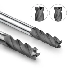
Dialing in reliable graphite end mill speeds and feeds requires treating cutting parameters as an interconnected system. Graphite density, grain size, cutter diameter, and axial depth directly dictate how forces transfer into the part. Instead of pushing for maximum material removal, we fine-tune cutting values based on spindle harmonics, airborne dust density, and microscopic edge wear.
Graphite End Mill RPM and Cutting Speed
Setting spindle RPM requires calculating actual surface footage (SFM) rather than spinning the spindle arbitrarily fast. A set RPM yields vastly different peripheral cutting speeds across different tool diameters. We often see operators run micro-end mills at large-tool speeds, starving the cut and dramatically accelerating cutting edge abrasion.
When optimizing graphite end mill RPM, we calculate surface speed based on tool diameter and graphite abrasiveness. Running too slow causes micro-chipping from high cutting pressures, while excessive RPM creates frictional rubbing and airborne dust. We increment surface speed gradually, monitoring spindle load and cutter wear to pinpoint the ideal machining window.
Graphite End Mill Feed Rate and Chip Formation
Evaluating table feed means checking whether the cutting edge shears clean micro-chips or pulverizes material into fine dust. Because graphite lacks ductility, the feed rate directly controls the fracture thickness per tooth. An overly conservative feed rate causes the tool to rub rather than cut, generating friction that rapidly dulls cutting edges.
We synchronize the graphite end mill feed rate with flute count, RPM, and radial step-over. Increasing flute count without raising table feed thins the chip load, accelerating abrasive tool wear. Conversely, overfeeding spikes instantaneous cutting pressure, breaking fragile electrode ribs. The goal is maintaining a crisp shear that evacuates chips without destructive tool rubbing.
How Depth of Cut and Step-Over Affect Graphite Milling
Controlling axial depth of cut (AP) and radial step-over (AE) regulates the volume of material removed per pass. Pushing depth of cut to tool limits often overloads the delicate structural integrity of the graphite itself. Thin walls and deep ribs can break apart completely under excessive radial cutting forces and poor dust evacuation.
We balance depth of cut and step-over across distinct roughing, semi-finishing, and finishing sequences. Aggressive step-overs suit bulk roughing when machine rigidity and vacuum dust collectors allow it. For finishing passes, dropping engagement stabilizes tool pressure and preserves crisp corners. When surface texture degrades, reducing cut engagement is far more effective than simply ramping up RPM.
Cutting Mechanisms for Small Diameter Graphite End Mills in Precision Graphite Machining
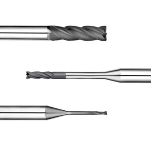
Milling micro-features, thin ribs, and deep slots in graphite electrodes presents distinct mechanical challenges. A tiny cutter may show no visual flaws, yet parts quickly suffer dimensional drift, corner chipping, and rough wall textures. We often see shops scale down cutter size without reducing cutting loads or shank stick-out. Running standard parameters on miniature tooling causes rapid edge wear and early tool failure.
Deploying small-diameter graphite end mills demands strict control over rigidity, tool runout, and cutting forces. Because shank stiffness scales with the fourth power of diameter, even tiny deflections ruin brittle graphite edges. Successfully milling micro-electrodes requires redesigning your tool paths and feeds rather than just swapping tool sizes in the CAM program.
Cutting Forces and Rigidity of Small Diameter Graphite End Mills
Tool rigidity drops sharply with every millimeter reduction in cutter shank diameter. When slotting deep cavities or cutting micro-ribs, the tool deflects under low spindle loads. We often diagnose out-of-tolerance profiles where the culprit is excessive tool overhang rather than code errors. Even minimal deflection alters the cutting angle, inducing unpredictable gouging and rib breakage.
Running small-diameter graphite end mills successfully requires minimizing stick-out and holding tool runout below 3 microns. The goal is managing cutting loads within the tool’s true elastic limits. Rather than slashing all feeds, we trim radial step-overs while holding stable chip loads per tooth. For delicate electrodes, stable engagement matters far more than raw cutting speeds.
How Small Diameter Tools Affect Graphite Surface Finish
Finishing thin walls requires understanding how low tool rigidity affects the carbon matrix. Dynamic chatter, spindle runout, and micro-chipping telegraph directly onto finished electrode surfaces. During deep sidewall passes, uneven edge engagement leaves distinct washboard chatter marks. Even with unchanged CAM settings, an unstable tool produces inconsistent surface finishes from part to part.
Evaluating surface finishes in graphite machining requires monitoring tool deflection alongside workpiece roughness. When surface finishes degrade mid-cycle, we immediately check the tool edge for micro-fractures before adjusting spindle speeds. For mirror-like EDM finishes, light multi-pass step-overs and consistent tool contact consistently beat heavy cleanup passes.
How to Reduce Edge Chipping with Small Diameter Graphite End Mills
Sudden edge blowout is disastrous when milling thin-walled graphite electrodes. Because graphite fractures under tensile stress, cutting spikes at corners and wall transitions blow out fine details. An interrupted cut can easily snap micro-flutes or fracture delicate workpiece features. We prevent catastrophic chipping by programming arc lead-ins, decreasing cut depths, and shortening tool stick-out.
Eliminating edge chipping on small diameter graphite end mills requires a systematic check of your setup. We inspect collet concentricity, tool stick-out, corner radius geometries, and entry ramping paths. Smoothing corner toolpaths prevents the cutter from plowing material at direction changes. Tailoring your milling strategy to brittle micro-fracture dynamics ensures clean edges and repeatable tolerances.
Long Life Graphite End Mills: Mechanisms of Tool Wear and Service Life
In high-volume graphite electrode production, tool failure rarely happens through catastrophic breakage. Instead, tool life degrades gradually as cutting edges lose their micro-radius and fine dust builds up in the cavity. A job often begins within tolerance, but continuous flank wear eventually causes dimensional drift and edge blowout. In our machining audits, poor dust evacuation and constant secondary friction prove to be the primary drivers of premature failure.
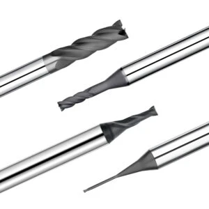
A genuine long-life graphite end mill is defined by its ability to hold tight tolerances across thousands of linear inches. Achieving maximum tool life requires looking beyond raw runtime to evaluate how tool substrates, diamond coatings, and graphite grain sizes interact. Long-term edge integrity requires balancing mechanical cutting loads with effective dust evacuation at the spindle.
How Graphite Dust Accelerates Graphite End Mill Wear
Fine graphite dust acts as an abrasive grinding compound inside the active cut zone. While airborne particles seem light, unevacuated dust swirls across the cutter’s flank and rake faces with every revolution. When extraction airflow is weak, trapped particles re-enter the cut zone, creating secondary abrasive rub that rapidly erodes sharp relief angles and destroys edge integrity.
Preventing accelerated tool wear requires optimizing airflow dynamics rather than simply slowing down the spindle. We analyze dust flow from generation to evacuation to ensure particles leave the cut immediately. Position high-velocity vacuum shrouds and targeted dry air blasts directly at the tool-workpiece interface to prevent abrasive dust recutting.
Achieving Long Tool Life with Diamond Coated Graphite End Mills
Machining high-density, fine-grain graphite blocks requires exceptional wear resistance to prevent rapid tool failure. Continuous abrasive friction erodes standard cutting edges within minutes, while diamond-coated graphite end mills provide a durable barrier that protects the carbide substrate. Maintaining original edge geometry across long shifts is what separates profitable batch production from constant offset tracking.
However, a diamond coating cannot compensate for excessive spindle runout or aggressive tool deflection. An unbalanced toolholder or an overextended cutter shank will micro-chip the diamond layer, triggering rapid delamination. Achieving long tool life requires pairing high-adhesion diamond coatings with rigid setups, balanced toolholders, and controlled chip loads.
Extending Graphite End Mill Tool Life Through Cutting Parameters
Pushing parameters to the absolute limit usually leads to unpredictable edge breakdown. In our CNC shop, we track linear cut distance, part quantities, and flank wear land growth to systematically extend graphite end mill tool life. Parameter-induced failure typically stems from excessive chip loads overloading the cutting edge rather than high surface footage alone.
We dial in chip load per tooth first, then scale spindle RPM and table feed to match the specific graphite grade. Bulk roughing passes utilize moderate radial stepovers to manage tool pressure, while finishing programs drop cut engagement to protect critical corners. Maintaining stable cutting parameters ensures predictable tool life and lets you swap tools before dimensional drift compromises the electrode.
How to Choose the Best End Mill for Graphite Machining: From Cutting Mechanisms to Custom Graphite End Mills
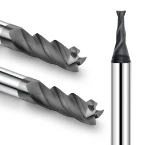
Selecting the right tooling for graphite electrode production is never about finding a single magic spec. Flute counts dictate chip evacuation and tooth load, tool diameter governs shank deflection, and solid carbide substrates provide edge stability. Meanwhile, diamond coatings resist continuous flank abrasion, and differing graphite densities alter cutting forces across identical toolpaths.
Determining the best end mill for graphite machining requires reverse-engineering your setup from specific part features rather than guessing at catalog specs. We evaluate graphite grain classification, roughing allowances, thin-rib requirements, and required surface finishes. Matching your tool’s substrate, flute geometry, and coating to the actual cutting environment guarantees repeatable tolerances and eliminates premature tool failure.
How to Select the Best Graphite End Mills Based on Graphite Grade
Our process always starts by identifying the exact graphite material, because grain diameter and Shore hardness directly dictate tool wear patterns. Coarser, porous graphite grades machine with low cutting resistance, allowing for sharper edge preparations and aggressive feeds. Conversely, ultrafine, high-density graphite generates extreme abrasive wear, demanding high-adhesion diamond coatings and reinforced relief angles to prevent edge breakdown.
Never rely solely on trade names or generic labels like “electrode graphite.” We review the material’s micro-grain sizing, bulk density, and electrical resistivity before matching it to the part geometry. Identifying the best graphite end mills requires evaluating manufacturer material spec sheets alongside your required machining tolerances, ensuring the cutting edge holds up against the material’s specific abrasive rating.
Selecting Graphite End Mills for Roughing vs Finishing
Roughing and finishing passes require completely different tooling configurations to remain cost-effective. Heavy roughing demands large flute valleys for rapid dust evacuation, rigid tool cores to absorb vibration, and maximum material removal rates. Finishing shifts the priority to runout accuracy below 3 microns, razor-sharp edge integrity, and micro-deflection control for tight EDM tolerances.
When planning roughing operations, choose large-diameter, high-clearance cutters to clear abrasive dust without packing. For thin ribs, sharp internal radii, or 3D contours, switch to smaller finishing tools and reduce radial engagement to minimize cutting pressure. Dedicated roughing and finishing tools consistently outperform attempts to run a single graphite end mill across an entire cycle.
When to Opt for Custom Graphite End Mills
Off-the-shelf tooling should always be your starting baseline. We only recommend custom graphite end mills when catalog tools force compromises between reach, core stiffness, and cavity depth. Deep, narrow EDM ribs, non-standard slot widths, or tiny corner radii often require custom neck reliefs, specialized taper angles, or non-standard flute lengths to eliminate chatter.
Before commissioning a custom design, pinpoint the exact mechanical failure of standard cutters. We SAMHO engineer custom profiles directly from part CAD models, targeting specific reach depths, corner blend radii, and reinforced neck diameters. Purpose-built custom graphite end mills eliminate tool deflection and wall gouging in deep cavities, delivering dependable finishes where standard tools fail.
How to Choose the Best Graphite End Mill for CNC Machining
Selecting the right tool requires evaluating every factor as a complete system. Material density sets the baseline abrasion rate, flute profile dictates dust clearance, the carbide substrate ensures fracture resistance, and diamond coatings halt flank wear. Dialing in spindle RPM, chip load per tooth, and depth of cut ensures cutting forces remain well within the tool’s stable limits.
Finding the best graphite end mill for CNC machining comes down to defining your operational constraints. Identify your graphite grade, feature geometry, stick-out length, and target Ra surface roughness before ordering tooling. Auditing your parameters against real-world shop-floor cutting dynamics will always yield higher part yields and lower tooling costs than searching for a universal cutter.






