


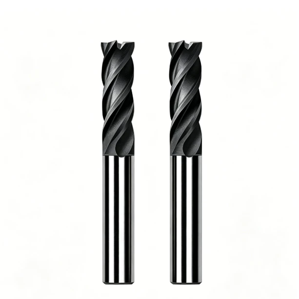
finish was flawless. Yet midway through the batch, flank wear accelerated rapidly, cutting edges developed micro-chipping, and the surface finish deteriorated. While machinists often blame tool batches or raw material hardness, our shop-floor testing revealed the real culprit: uncontrolled cutting zone temperature.
Graphite machining behaves uniquely compared to metal cutting. Material characteristics like grain size, porosity, bulk density, and graphite thermal conductivity govern how heat generates and dissipates during dry milling. Graphite cutting temperature is never dictated by spindle speed alone. Instead, it is the cumulative result of tool geometry, surface footage, chip load, depth of cut, and evolving edge condition.
In high-speed milling, friction along the tool-workpiece interface and localized brittle fracture generate significant thermal energy. This interaction forms the core graphite cutting heat mechanism. Because graphite dust removal relies on air blasts rather than flood coolant, the graphite cutting heat dissipation rate depends heavily on material conductivity and evacuation velocity to prevent localized heat buildup.
Cutting temperature does not operate in isolation; it accelerates a destructive feedback loop. As abrasive wear rounds the cutting edge, rubbing friction increases dramatically, spiking the local cutting temperature. This compounding cycle directly drives rapid graphite cutting tool wear and shortens overall graphite cutting tool life, leading to dimensional drift, edge blowout, and rougher Ra values on critical mold components.
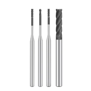
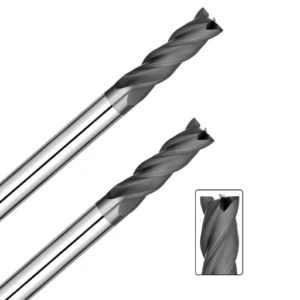
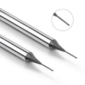
Selecting the right tooling requires looking beyond flute count and base carbide grades. For continuous finishing runs, thermal stability and edge retention are paramount. Investing in a premium diamond-coated graphite end mill pays off because chemical vapor deposition (CVD) diamond maintains a sharp edge across long cycle times. This edge retention reduces friction spikes and stabilizes machining consistency.
To optimize high-precision operations, machinists must look deeper into thermal dynamics at the cut zone. Understanding the relationship between cutting parameters, friction behavior, and thermal evacuation is the only reliable way to separate tooling failure from thermal degradation. Mastering these heat mechanisms ensures predictable tool life and tight tolerances across every batch.
Graphite Cutting Temperature and Material Properties in Machining
In precision graphite electrode machining, we never evaluate cutting temperature in isolation. When switching graphite grades under identical CNC parameters, shops often see sudden shifts in tool wear rates and surface finish quality. Bulk density, grain structure, porosity, and thermal conductivity govern these thermal variations in the cut zone. These graphite material properties actively dictate brittle fracture behavior, cutting friction, and thermal dissipation during milling.
When tool temperature, dust particle size, or edge integrity drift from baseline values, we avoid immediately tweaking feeds and speeds. Instead, we inspect raw material consistency first. Subtle microstructure variations alter shear forces, localized rubbing, and heat evacuation paths during finishing passes. Isolating these raw material variables prevents machinists from falling into costly, blind parameter trial-and-error cycles.
How Do Graphite Material Properties Affect Cutting Temperature?
On many electrode jobs, roughing passes run smoothly while finishing passes quickly develop micro-chipping and flank wear on identical tool paths. Grain size and pore distribution dictate how graphite fractures ahead of the cutting edge. Higher localized fracture resistance increases mechanical rubbing against the relief angle, accelerating localized friction and thermal buildup at the tool tip.
Evaluating graphite cutting temperature requires looking at material properties alongside cutting speed, feed per tooth, depth of cut, and edge prep. Never assume a specific grade naturally runs hotter or cooler. Watch how microstructure shifts align with cutting load spikes, dust dispersion patterns, and tool wear. This correlation provides actionable diagnostic data for tight-tolerance electrode jobs.
How Does Graphite Thermal Conductivity Affect Heat Transfer During Machining?
Thermal dynamics in graphite milling differ fundamentally from metal cutting because graphite conducts and sheds heat rapidly without plastic deformation. The material’s graphite thermal conductivity directly dictates whether thermal energy dissipates into the bulk workpiece or concentrates at the tool edge. However, anisotropic grain alignment, internal porosity, and binder matrix variations alter theoretical heat transfer rates in real-world milling.
When anomalous edge temperatures or workpiece burnishing occur, we check whether thermal energy is evacuating cleanly or trapping along the tool interface. Tool sharpness, surface footage, and air blast velocity directly influence this thermal balance. Graphite cutting heat dissipation cannot be evaluated using material data sheets alone; it must be measured against dynamic cutting conditions.
The Relationship Between Graphite Density, Grain Size, and Cutting Temperature
Switching graphite grades demands a close look at density and average grain size. Ultra-fine grain graphite fractures cleanly with lower cutting resistance, while coarser or lower-density grades cause abrasive micro-chipping and edge rubbing. These microstructural differences drive cutting force spikes, alter dust particle morphology, and create sharp fluctuations in cutting zone temperature.
If identical diamond end mills and CNC programs yield inconsistent tool life across material lots, compare bulk density, grain size, and pore uniformity first. In light finishing passes, the link between microstructure and thermal load is rarely simple. It is governed by a balance of brittle fracture mechanics, tool rubbing, and thermal diffusion across the cut zone.
Graphite Cutting Heat Mechanism: How Is Heat Generated During Graphite Machining?
During high-speed graphite electrode finishing, tool edges gradually degrade over long cycles, leading to sudden shifts in surface integrity. When cut-zone heat fails to evacuate cleanly, friction dynamics between the tool flank and graphite workpiece change rapidly. Understanding the core graphite cutting heat mechanism means identifying where thermal energy originates and why localized friction intensifies under continuous dry milling.
Assessing heat generation requires looking past ambient workpiece temperature to the microscopic tool-graphite interface. Thermal buildup stems from dynamic interactions between cutting forces, abrasive contact, brittle micro-fracture, dust evacuation, and progressive tool wear. Analyzing these heat sources, fracture behaviors, and parameter dynamics provides the actionable data needed to stabilize precision electrode production.
Where Does Graphite Cutting Heat Come From?
Cutting heat in graphite machining results from concurrent mechanical and thermal interactions rather than simple surface contact. As the cutter edge engages the stock, it overcomes internal carbon bonds through localized brittle fracture, transforming mechanical energy directly into heat. Simultaneously, high-velocity sliding friction between the cutting edge, relief face, and abrasive graphite dust generates substantial thermal loads.
Material microstructure—including grain boundary cohesion, bulk density, and porosity—directly alters these heat generation pathways. Coarser grains change fracture dynamics and contact frequency, preventing graphite cutting heat from remaining at a static baseline. When identical milling programs produce abnormal wear across different lots, checking microstructure and interface friction yields faster diagnostic results than blaming tool coatings alone.
How Are Frictional Heat and Deformation Heat Generated During Graphite Machining?
Unlike metal cutting, which generates heat through continuous shear-zone plastic deformation, graphite undergoes brittle micro-cracking and particle spalling. Heat originates from microscopic fracture energy and abrasive friction along the tool’s rake and flank faces. As cutting edges develop micro-wear, contact land width expands, causing abrasive graphite particles to grind against the tool and spike thermal output.
Applying standard metalworking deformation models to the graphite cutting mechanism leads to flawed machining strategies. Grain diameter, porosity, edge sharpness, and tool path direction all govern how carbon particles fracture and shear away. Once edge rounding occurs under fixed feeds and speeds, rubbing friction escalates, driving simultaneous spikes in cutting temperature and edge chipping.
How Do Cutting Speed and Feed Rate Affect Heat Generation in Graphite Machining?
A common CNC shop misconception is that reducing the feed rate or maxing out spindle RPM will automatically cool the cut zone. Higher cutting speeds increase tooth engagement frequency and thermal cycles per minute, while feed rate dictates chip load and mechanical tool pressure. Evaluating cutting speed and feed rate requires balancing cutter diameter, flute count, stepover, and specific graphite grades.
Under-feeding is especially destructive; an excessively low chip load forces the tool to rub and burnish rather than cleanly shear the carbon matrix, trapping excessive heat at the tip. Optimizing graphite cutting parameters demands balancing material removal rates, tool load, thermal evacuation, and surface finish rather than chasing unrealistic minimum cutting temperatures.
Heat Dissipation in Graphite Cutting: How Is Heat Dissipated During Graphite Machining?
During continuous graphite electrode finishing, cut-zone heat does not always evacuate as quickly as machinists expect. The cutting tool, workpiece, fine carbon dust, and surrounding airflow interact constantly, exchanging thermal energy across microscopic contact points. Effective graphite cutting heat dissipation is not about tracking a static property value; it requires maintaining a steady equilibrium between heat generation and thermal evacuation.
When tool edges wear down or dust extraction weakens, cutting dynamics shift rapidly despite identical CNC programs. A rounded edge increases contact area and friction, accelerating localized heat accumulation along the cut zone. Troubleshooting temperature spikes requires looking beyond surface footage and feed rates to inspect material conductivity, tool sharpness, and active airflow around the tool tip.
How Does Graphite Thermal Conductivity Affect Heat Dissipation?
Bulk graphite thermal conductivity controls how quickly thermal energy diffuses away from the shear interface and into the parent material. However, high conductivity does not guarantee low tool temperatures in practical milling. Because the actual contact zone is microscopic, final temperatures depend heavily on heat generation rates, contact duration, and internal pore structures across different graphite grades.
When two graphite grades exhibit vastly different tool wear rates under identical parameters, evaluate thermal conductivity alongside cutting forces and brittle fracture dynamics. Our shop floor focus centers on continuous heat evacuation from the localized cutting zone rather than relying solely on raw data sheet ratings. This holistic approach provides an accurate picture of real-world thermal transfer.
How Is Graphite Cutting Heat Transferred Between the Tool, Workpiece, and Air?
In high-speed graphite milling, the cut zone acts as an open, dynamic heat exchange zone. Thermal energy divides across three distinct paths: transferring into the tool substrate, conducting into the workpiece, and evacuating with airborne dust and high-velocity air streams. Tracking these graphite cutting heat paths helps machinists diagnose why a cutter suddenly experiences rapid flank wear or coating failure.
Poor dust extraction directly disrupts this thermal balance. When particulate builds up in tight features, secondary rubbing between the tool and loose carbon particles increases friction and traps heat at the edge. If cutting tool wear spikes unexpectedly, inspect air blast positioning, vacuum airflow velocity, and cut-zone cleanliness before rewriting machining parameters.
Why Does Heat Dissipation in Graphite Machining Differ From Metal Machining?
Metal cutting removes material through continuous shear-zone plastic deformation, carrying the bulk of cutting heat away within continuous metal chips. Graphite machining relies entirely on brittle fracture, micro-cracking, and fine powder ejection without chip formation. Because cooling mechanisms differ completely, metalworking flood coolant strategies cannot be applied to dry graphite electrode milling.
Graphite machining generates high volumes of fine, abrasive dust that alters the immediate cutting environment around the end mill. Finishing tight-tolerance electrodes requires stabilizing cut-zone friction and maintaining continuous particulate evacuation via air streams. Applying wet coolant creates an abrasive slurry that ruins surface finish, accelerates abrasive wear, and fouls EDM dielectric downstream.
How Does Graphite Dust Affect Cutting Heat and Heat Dissipation?
Dust evacuation performance serves as a vital diagnostic indicator of cutting stability on the CNC floor. While suspended dust particles are not primary heat generators, trapped powder inside deep cavities or narrow slots causes abrasive secondary rubbing against the tool relief. This trapped particulate increases friction, elevating localized temperatures and driving premature tool failure.
Efficient vacuum extraction and directed air blasts prevent graphite particles from re-cutting and packing along the flutes. Maintaining high-velocity airflow ensures continuous heat evacuation away from the cutting interface. When dealing with thermal spikes or rapid graphite cutting tool wear, evaluate dust extraction velocity, air nozzle orientation, and tool wear state simultaneously.
How Does Graphite Cutting Temperature Affect Tool Wear?
In precision graphite electrode machining, a common failure pattern involves sharp cutting edges degrading prematurely into heavy flank wear and edge chipping. Blaming this deterioration entirely on raw material abrasiveness overlooks the root cause. Cutting friction, thermal buildup, and edge rounding interact continuously, making graphite cutting temperature a primary driver of premature tooling failure.
When tool wear accelerates unexpectedly, looking solely at carbide grades or material data sheets provides an incomplete picture. Machinists must monitor spindle load, vacuum extraction velocity, edge integrity, and surface finish simultaneously. During extended finishing runs, minor edge breakdown alters contact dynamics, triggering a destructive feedback loop of rising thermal loads and compounding tool wear.
How Do High Cutting Temperatures Accelerate Tool Wear?
Thermal spikes in graphite milling rarely cause instant catastrophic fracture; instead, localized heat softens carbide binders and weakens chemical vapor deposition (CVD) coatings. Combined with constant carbon particle rubbing, elevated temperatures accelerate abrasive micro-abrasion along the relief angle. High temperatures serve as a thermal catalyst that drastically speeds up mechanical wear mechanisms.
To detect thermally accelerated wear, compare acoustic feedback and dust characteristics between early and late machining stages. When surface roughness climbs and cutting noise changes under identical parameters, cut-zone heat accumulation is usually the underlying cause. Tracking these shop-floor symptoms provides reliable diagnostic clarity without requiring complex thermocouple setups.
What Is the Relationship Between Graphite Cutting Heat and Tool Wear?
The interaction between graphite cutting heat and tool degradation forms a continuous cycle on the CNC machine. A razor-sharp cutting edge fractures graphite cleanly with minimal tool pressure and controlled rubbing. Once micro-chipping or abrasive flank rounding begins, cutting resistance increases, driving up frictional heat generation across the expanded contact area.
When tool life drops unexpectedly, analyzing the entire wear progression reveals more than tracking total spindle run time. Flank land growth, micro-chipping, and dust packing alter how heat evacuates from the cutting zone. Controlling this thermal-wear cycle through balanced parameters stabilizes tool life far better than arbitrary feeds-and-speeds adjustments.
How Do Graphite’s Abrasiveness and Cutting Temperature Jointly Affect Tool Wear?
Graphite grade variations in grain structure, bulk density, and porosity dictate brittle fracture behavior during milling passes. Fine carbon particles constantly abrade the tool substrate, and when this abrasive scrubbing combines with elevated localized temperatures, edge breakdown accelerates. Real-world graphite cutting tool wear is the combined outcome of high thermal energy and mechanical abrasion.
Lowering cutting speeds indiscriminately to drop temperatures often backfires by reducing chip clearance efficiency. Excessively low feeds cause the tool edge to rub and burnish the workpiece rather than shearing cleanly. Maintaining proper chip load and effective air evacuation balances mechanical cutting action, keeping thermal accumulation within safe operational limits.
How Do Diamond Coated Graphite End Mills Reduce Tool Wear?
For long-run graphite electrode production, switching from uncoated carbide to a diamond coated graphite end mill dramatically improves process stability. The extreme hardness and low coefficient of friction of diamond resist abrasive scrubbing, preserving edge sharpness across lengthy cycles. This edge retention prevents friction spikes and maintains dimensional accuracy across dozens of workpieces.
However, diamond coatings cannot compensate for poor tool paths, improper chip loads, or weak dust extraction. If cutting parameters force edge rubbing, even premium diamond layers can delaminate under excessive thermal-mechanical shock. Establishing balanced cutting parameters first allows diamond coatings to maximize graphite cutting tool life and deliver consistent surface finishes.
Graphite Cutting Temperature and Tool Life
In high-volume graphite electrode machining, tool life follows two distinct phases: an initial steady cutting state and a secondary rapid breakdown phase. Shops frequently see excellent surface finish across early parts, followed by sudden edge degradation, dimensional drift, and surface tearing. Tracking total spindle run hours alone cannot pinpoint the root cause when cutting friction, thermal buildup, and micro-fracture dynamics change over time.
Real-world tool life is never a static catalog number; it shifts with graphite grade, grain size, bulk density, tool geometry, parameter balance, and dust extraction efficiency. When evaluating overall graphite cutting tool life, monitoring cut-zone thermal fluctuations provides early warning signs of tool failure. Identifying these thermal transitions helps operators swap inserts or end mills before catastrophic part rejection occurs.
How Does Cutting Temperature Affect Graphite Cutting Tool Life?
Evaluating cutting temperature requires tracking thermal accumulation across the entire milling cycle rather than focusing on a single moment. While sharp cutting edges fracture carbon cleanly with minimal heat buildup, gradual edge rounding expands the tool-workpiece contact patch and increases sliding friction. This continuous thermal exposure softens tool substrates and coatings, drastically reducing overall graphite cutting tool life.
When a cutter machines early electrodes within tolerance but degrades rapidly on subsequent cycles, inspect flank land growth, acoustic pitch shifts, and dust dispersal patterns. These physical indicators reveal thermal buildup long before total edge blowout. Relying on dynamic cutting feedback delivers far more consistent tool life predictions than theoretical manufacturer run-time charts.
Why Does Graphite Cutting Temperature Rise Further After Tool Wear Occurs?
As abrasive carbon particles wear down the cutting edge, the tool transitions from clean brittle fracturing to intense mechanical rubbing. This dulling action increases cutting resistance and expands flank contact land, driving up frictional heat along the cut zone. Running a dull tool past its useful edge life accelerates this thermal spike, compromising part accuracy.
Machining viability cannot be judged solely by whether the cutter still removes material. Even if a machine finishes a cycle, surface finish, rib definition, and corner sharpness may already be out of tolerance. Continuing to run worn tools triggers a destructive feedback loop: progressive wear increases friction, driving up localized temperatures and causing compounding edge breakdown.
How Can Cutting Parameters Extend Graphite Cutting Tool Life?
Optimizing CNC programs to extend tool life requires balancing cutting speed, feed per tooth, and radial/axial depths of cut rather than simply dropping RPM. An excessively light chip load causes the tool edge to rub and burnish, generating destructive friction without removing material efficiently. Conversely, overloading the cutter promotes edge chipping and sudden structural failure under high cutting pressure.
When troubleshooting inconsistent tool wear across production runs, adjust chip load to match tool diameter, flute geometry, and raw material grain structure. Separate parameter sets clearly between high-efficiency roughing and light finishing passes. A balanced parameter strategy stabilizes cutting loads, manages thermal buildup, and extends reliable graphite cutting tool life across long production batches.
Can Diamond Coated Graphite End Mills Extend Tool Life?
For long-run graphite electrode production, using a diamond coated graphite end mill provides superior edge retention against abrasive carbon dust. Uncoated carbide tools experience rapid flank wear and edge rounding, causing early dimensional drift. The extreme hardness and low friction coefficient of real diamond coatings maintain sharp cutting edges across extended cycle times.
However, a diamond coating is not a standalone fix for aggressive or mismatched parameters. Inadequate dust extraction, poor tool paths, or severe tool deflection can quickly cause premature coating delamination. Pairing optimized feeds, speeds, and vacuum extraction with high-quality diamond tooling ensures true edge stability, tight electrode tolerances, and predictable tool life.
Graphite Cutting Temperature and Graphite Machining Surface Quality
Finishing precision graphite electrodes requires looking beyond raw Ra roughness values. Workpieces may meet basic dimensional callouts while harboring subsurface micro-chipping, carbon grain pull-out, or uneven surface topography under magnification. Graphite cutting temperature fluctuates directly with tool wear, brittle fracture mechanics, and edge stability. Evaluating these cutting parameters together ensures predictable part geometry across production batches.
Continuous finishing runs reveal sharp quality differences between the first and fiftieth parts. As cutting edges dull, rubbing friction and mechanical tool loads shift, degrading surface consistency under identical CNC code. Consistent graphite machining surface quality is not just a tooling spec; it is the cumulative outcome of edge integrity, material grain structure, and cut-zone thermal balance.
How Does Cutting Temperature Affect Graphite Machining Surface Quality?
Thermal spikes rarely create obvious thermal burns on carbon workpieces; instead, heat alters brittle fracture dynamics at the tool tip. As edge breakdown progresses, sliding friction intensifies localized thermal loads. Elevated temperatures and fluctuating cutting forces cause loose micro-particle pull-out and fractured electrode edges rather than clean shearing along grain boundaries.
When uniform finishes degrade into matte or pitted textures, avoid immediately blaming temperature alone. Inspect cutting edge wear lands, spindle load trends, and material grain consistency first. The link between thermal spikes and degraded surface finish is driven by mechanical rubbing and edge breakdown rather than a single isolated temperature value.
Why Can High Cutting Temperatures Lead to Graphite Surface Defects?
Extended machining runs often exhibit corner blowout, rib chipping, and striated finishes without any parameter changes. Inspecting the tool under a microscope typically reveals extensive flank wear. This edge rounding alters material removal from clean shearing to abrasive micro-fracture, causing destructive graphite machining defects across delicate electrode features.
Dropping spindle speed indiscriminately often worsens surface finish by increasing contact dwell time and rubbing friction per revolution. Machinists must diagnose specific defects—such as particle pull-out, edge blowout, or surface pitting—before adjusting parameters. Pinpointing the failure mode determines whether the fix requires tooling changes, air blast adjustments, or feed rate optimization.
How Does Graphite Cutting Tool Wear Affect Graphite Surface Quality?
Tracking cutting edge condition provides the most reliable indicator of shifting surface finish in production. Sharp end mills cleanly shear carbon particles with minimal cutting pressure. Once flank wear or micro-chipping develops, the tool begins burnishing the graphite, causing rapid graphite cutting tool wear and rougher surface finishes.
When surface quality drifts under proven parameters, inspect the cutting edge before rewriting CNC code. Light finishing passes are highly sensitive to edge breakdown, where slight rounding degrades fine rib definition and sharp corners. Pairing visual tool inspection with acoustic monitoring indicates the exact moment to perform a tool offset change.
How Can Reducing Cutting Heat Improve Graphite Machining Surface Quality?
Process optimization in graphite milling should never focus solely on chasing minimum temperatures. The true objective is maintaining a balanced cutting state with steady chip loads and minimal tool rubbing. Adjust surface footage, chip load, and stepover incrementally while monitoring edge wear, surface finish, and dust evacuation patterns.
Stabilizing long finishing runs requires verifying air blast velocity and vacuum extraction to prevent trapped dust from re-cutting. Achieving superior graphite machining surface quality demands a complete process approach: maintaining sharp edges, preventing tool rubbing, and evacuating cutting heat through high-velocity air streams.
How to Control Graphite Cutting Temperature and Optimize Graphite Machining?
When tool wear accelerates or electrode finishes degrade, hastily slashing spindle RPM is rarely the answer. Stabilizing the cut zone requires evaluating material density, grain structure, tool geometry, cutting speed, chip load, and vacuum extraction velocity together. Graphite cutting temperature is the direct outcome of dynamic interactions between mechanical loads, tool sharpness, and dust evacuation paths.
Shop floor optimization should prioritize stable shearing over chasing theoretical minimum temperatures. Watch for shifts in acoustic pitch, dust particle size, and edge wear progression across production cycles. Isolating variables step-by-step pinpoints whether thermal degradation stems from parameter mismatches, substrate wear, or poor chip evacuation.
How to Optimize Graphite Cutting Speed and Feed Rate?
Setting optimal CNC feeds and speeds requires tailoring parameters to cutter diameter, flute count, material density, and cut depth. Never rely on generic speed charts; ensure the chip load per tooth maintains true shearing without rubbing. An excessively low feed forces the edge to burnish the carbon, spiking frictional heat, while over-feeding risks severe edge chipping.
Troubleshooting an elevated graphite cutting temperature requires making incremental parameter changes—adjusting one variable at a time while monitoring wear lands. Tracking spindle load, acoustic feedback, and cycle times provides real-world clarity on cutting efficiency. This data-driven approach confirms whether thermal buildup stems from surface footage, feed rate, or raw material variation.
How to Reduce Graphite Cutting Heat Through Tool Geometry?
Cutter geometry governs how edge pressure, relief angles, and flute space interact with the graphite matrix. Sharp cutting edges and optimized rake angles promote clean brittle fracture while minimizing unnecessary flank rubbing and thermal generation. Mismatched geometries—even under conservative speeds—trap cutting loads at the tool tip, driving up localized temperatures.
Deep ribs and narrow cavities demand tools with rigid cores, adequate flute gullets, and tailored helix angles to prevent dust packing. Roughing passes require rugged edge prep to absorb mechanical shock, while finishing passes need razor-sharp edges to prevent edge blowout. Selecting application-specific geometries stabilizes shearing action and enhances overall thermal management.
How to Select Diamond Coated Graphite End Mills to Control Tool Wear?
When uncoated carbide wears prematurely on high-density graphite, switching to high-grade diamond tooling is essential. Selection should consider substrate carbide grain size, edge prep, coating adhesion, and geometry. A premium diamond coated graphite end mill excels in long unattended finishing runs where tight tolerances and edge integrity are critical.
Evaluate diamond tooling by inspecting the cutting edge after dozens of parts rather than checking initial surface finish alone. True tool value lies in edge retention across extended cycle times. However, diamond coatings cannot offset improper feeds, heavy deflection, or poor dust extraction; balanced cutting parameters remain vital for maximum tool life.
How to Improve Graphite Heat Dissipation via Machining Parameters and Dust Extraction?
Managing cut-zone thermal buildup requires treating dust extraction as an integral part of the cutting process. In deep cavities, stagnant carbon dust re-cuts continuously, increasing friction and trapping heat against the tool flank. Correcting unstable graphite cutting heat dissipation demands verifying air nozzle angles, vacuum CFM, and localized extraction velocity before modifying program feeds.
Pair parameter optimization with high-velocity air evacuation to carry airborne particulate and thermal energy away instantly. Continuous dry milling stability depends on maintaining an equilibrium between heat generation and particulate removal. Evaluating part geometry, graphite grades, and machine extraction capacity holistically ensures long tool life and flawless electrode finishes.
FAQ: Graphite Cutting Temperature
Cutting zone temperature in graphite milling is never governed by a single isolated variable. Raw material microstructure, surface footage, chip load per tooth, tool wear, and vacuum extraction velocity all interact continuously. When diagnosing premature tool failure, surface pitting, or dimensional drift, use these shop-floor FAQs to evaluate your machining setup.
What Is the Cutting Temperature of Graphite Machining?
Graphite milling does not produce a single, universal cutting temperature because thermal loads vary across grades, tool geometries, and cycle times. Rather than chasing a theoretical temperature number, machinists should track thermal generation rates, heat evacuation efficiency, and wear progression. Accurately assessing graphite cutting temperature requires evaluating the specific carbon grade alongside active CNC parameters.
Why Does Graphite Generate Heat During Machining?
Thermal energy in graphite milling originates from brittle micro-fracture energy, tool flank rubbing, and continuous particulate friction along the relief angle. Even with conductive graphite, the microscopic tool contact zone generates intense localized heat. Understanding the graphite cutting heat mechanism means inspecting cutting edge sharpness, chip clearance, and dust evacuation paths together.
How Does Graphite Thermal Conductivity Affect Cutting Temperature?
Bulk thermal conductivity controls how quickly cutting heat diffuses from the shear zone into the parent graphite electrode. However, internal grain size, binder distribution, porosity, and surface footage heavily alter real-world thermal transfer rates. High graphite thermal conductivity helps dissipate heat, but it cannot prevent thermal buildup if tool rubbing or inadequate dust extraction occurs.
Does Cutting Temperature Affect Graphite Cutting Tool Wear?
Thermal spikes interact directly with mechanical friction and cutting loads to accelerate cutting edge breakdown. As flank wear develops, the wider contact patch increases sliding friction, driving up localized heat and softening carbide substrates. When troubleshooting abnormal graphite cutting tool wear, inspect wear land patterns, parameter balance, and air blast velocity simultaneously.
Does Cutting Temperature Affect Graphite Cutting Tool Life?
Elevated cut-zone temperatures shorten usable tool life by accelerating abrasive micro-chipping and coating degradation over extended cycles. A sharp tool cuts cleanly, but progressive edge wear triggers a compounding cycle of rising heat and accelerated breakdown. Maximizing graphite cutting tool life requires balancing feed rates, cutter coatings, and dust evacuation to keep temperatures stable.
Can a Diamond-Coated Graphite End Mill Reduce Cutting Heat?
Diamond tooling indirectly controls thermal spikes by maintaining razor-sharp cutting edges and offering an ultra-low friction coefficient. Preserving edge geometry prevents the severe tool rubbing and friction spikes caused by rapidly dulling uncoated carbide. While a diamond-coated graphite end mill stabilizes cutting temperatures, it must be paired with proper chip loads and high-velocity dust extraction.
How Can I Reduce Graphite Cutting Temperature?
Lowering cutting temperatures requires balancing surface footage, chip load, and depths of cut rather than blindly dropping spindle speed. Ensure the feed per tooth creates a clean shear without rubbing, and aim high-pressure air blasts directly at the tool tip to evacuate particulate. True process optimization maintains an equilibrium between material removal rates, tool life, and heat evacuation.






