


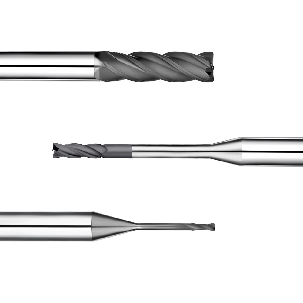
We recently worked on a project where a client milled two seemingly identical graphite grades. They ran the same CNC equipment, identical cutting parameters, and the exact same diamond-coated graphite end mill. Yet, tool wear rates varied dramatically. One grade left the cutting edge intact, while the other caused rapid edge wear and micro-chipping, compromising part tolerances and surface finish.
Machinists often blame poor tool quality, spindle runout, or feeds and speeds for this discrepancy. However, over a decade of hands-on machining shows the issue usually lies within the material itself. Graphite density and structural grade differences directly dictate machining performance. In high-density graphite machining, grain structure, porosity, and cutting resistance heavily influence tool life.
Clients frequently ask why the same graphite end mill delivers wildly different results across various grades. Why does tool wear accelerate on one block while remaining stable on another? The answer rarely comes down to simple bulk hardness or basic spec sheets. Instead, the real driver is how material density reflects internal microstructure.
Graphite density indicates particle bonding strength, grain size, and porosity distribution. These factors dictate whether the graphite fractures cleanly or generates harsh, abrasive dust that erodes cutting edges. Denser grades with finer grains often produce higher cutting forces and severe abrasion, accelerating tool wear.
When evaluating graphite tool life, never assume higher density automatically guarantees faster tool wear. We treat density as one critical variable alongside grain structure, chip evacuation, and tool geometry. Understanding the true relationship between graphite density and tool wear allows shops to tailor cutting strategies, optimize tool life, and maintain strict tolerances.
What Is Graphite Density? How It Affects Machining Characteristics
When evaluating graphite for real-world CNC projects, density is more than just a single number on a spec sheet. It serves as a direct indicator of internal microstructure, particle size, and porosity. Even when tooling, programs, and machines stay constant, switching material suppliers can alter cutting behavior due to underlying structural shifts.
From our machining experience, graphite density reveals critical material traits like abrasiveness, particle bonding, and fracture mechanics. Instead of jumping to conclusions based on bulk values alone, we assess test cuts directly. Watching cutting loads, dust evacuation, and early tool wear confirms how the material actually behaves in the cut.
Defining Graphite Density and Variations Across Grades
Graphite materials are far from uniform across industrial grades. While density defines mass per unit volume, machinists care most about how that mass is packed internally. Two electrode grades may look identical, but slight variations in grain size and compaction processes will produce completely different cutting resistance and wear patterns.
Higher density does not automatically mean a grade is harder to machine. In high-precision electrode work, we evaluate density alongside grain distribution and mechanical strength before cutting. Running quick test passes verifies tool load and edge integrity, ensuring the selected feeds and speeds match the material grade.
The Relationship Between Graphite Density, Microstructure, and Porosity
Graphite is an engineered composite of carbon particles, binder phases, and open pores. Higher graphite density typically indicates a tighter solid mass, but cutting resistance depends heavily on particle bonding. The way these micro-features fracture dictates whether cutting edges stay sharp or experience severe abrasive wear.
Porosity directly influences localized shock and mechanical stress on the cutting edge. In our shop, even moderate-density grades have caused rapid flank wear due to uneven particle clusters. Evaluating density, porosity, and grain uniformity together gives a clearer picture of real-world tool performance than density values alone.
How Graphite Machining Characteristics Vary with Density
Density fluctuations impact machining by altering cutting resistance, chip fracture modes, and graphite dust characteristics. In continuous milling operations, subtle differences in material density gradually accumulate into noticeable edge wear. This directly impacts final surface finish, dimensional stability, and overall tool life.
To accurately evaluate graphite machining characteristics, we track spindle load, cutting sound, and edge condition during initial passes. If multiple indicators shift at once, we fine-tune tool geometry, coating choices, and milling strategies. This data-driven approach prevents misdiagnosing tool wear and keeps CNC graphite processes stable.
Graphite Density and Tool Wear: Why Graphite Density Affects Tool Wear
In practical graphite electrode machining, switching to a different graphite grade often causes immediate shifts in spindle load and edge wear—even when tooling and CAM programs remain identical. Rather than blaming the cutting tool, machinists should inspect the raw stock. Density shifts alter internal compactness and particle bonding, directly changing how the material fractures against the cutting edge.
The correlation between graphite density and tool wear is rarely a simple linear line. High-density grades generate greater cutting resistance, but actual tool life depends on grain size, microstructural uniformity, and tool geometry. Tracking real-time spindle load, cutting sound, and dust texture provides a far more accurate assessment of wear than relying on density values alone.
Why High-Density Graphite Often Results in Higher Machining Loads
Milling dense graphite using feeds and speeds intended for standard grades creates a noticeable surge in spindle load during continuous cuts. Dense graphite contains more solid carbon mass and fewer voids per unit volume, forcing the tool edge to shear more solid material per revolution. This higher mechanical engagement immediately changes the cutting tone and machine load profile.
High-density graphite machining does not require drastically cutting your feeds across the board. We assess tool diameter, flute count, and depth of cut before modifying parameters. Feed per tooth is reduced only when chatter, chipping, or edge rounding appears, ensuring the machine stays within its optimal cutting window without sacrificing cycle time.
How Graphite Density Affects Cutting Force and Resistance
Graphite density directly influences the mechanical resistance a cutting edge encounters upon entry. However, overall cutting forces depend equally on particle size, porosity distribution, and edge sharpness. Structural variations between grades become especially visible during roughing passes with heavy radial engagement, causing distinct spindle load fluctuations.
Evaluating graphite density and cutting force requires viewing density as a contributing factor rather than the sole driver. When load spikes occur at steady parameters, machinists must inspect tool wear progression and actual depths of cut simultaneously. Eliminating tool deflection and chip packing first ensures that density-driven cutting resistance is accurately diagnosed.
How Graphite Density Alters the Graphite Milling Tool Wear Rate
Tool wear discrepancies between graphite grades rarely show up in the first few minutes of cutting; they emerge across extended cycle times. Continuous friction against abrasive carbon particles steadily rounds the cutting edge, leading to flank wear and micro-chipping. Tracking the graphite milling tool wear rate over prolonged runs provides the true measure of tool life.
Higher density does not automatically guarantee rapid tool failure. In our shop, we log cutting distance, material removal rates, and flank wear progression under a microscope. Analyzing this wear data against material density and grain uniformity helps establish predictable tool life curves and prevents unexpected tool failure during unattended machining.
How Graphite’s Abrasiveness Accelerates Tool Wear
Unlike metal cutting, graphite milling produces zero continuous chips or plastic deformation. Brittle fracture generates abrasive micro-particles and fine dust that continuously scour the cutting edge and relief surfaces. Uncoated carbide tools experience rapid flank wear from this severe abrasive action, making diamond-coated tooling essential for long-term edge retention.
Density and abrasiveness are not always directly proportional. Ultra-fine grain, high-density graphite with uniform bonding often machines cleanly with steady, predictable wear. Conversely, lower-density grades with irregular particle sizes can cause severe micro-chipping. Viewing graphite milling tool wear as an interaction between material microstructure, abrasive friction, and tool geometry ensures stable, repeatable machining results.
Differences in Tool Wear Between High-Density and Low-Density Graphite Machining
Comparing tool wear across different graphite densities under identical cutting conditions reveals how material structure impacts edge retention. One grade may preserve sharp cutting edges for hours, while another causes premature rounding and micro-chipping. Rather than tracking cycle time alone, we record total cut distance, material removal volume, spindle load, and wear mechanisms.
These tool wear variations stem from the direct interaction between graphite microstructure and cutting dynamics. Density provides a useful baseline, but it cannot predict tool wear rates on its own without considering grain size and porosity. Running standardized test cuts before locking in tooling and machining parameters ensures predictable tool life and process stability.
Graphite Milling Tool Wear in High-Density Graphite Machining
High-density graphite machining increases mechanical loads on cutting tools, especially during heavy roughing passes or deep radial engagements. Denser grain structures increase contact area between the carbon matrix and the cutting edge. Once minor edge wear begins, spindle load spikes become significantly more pronounced on high-density materials.
Solving wear issues in high-density graphite rarely requires drastically dropping spindle speeds. In our shop, we first optimize chip load per tooth and step-over values to match tool diameter and flute count. Controlling cutting forces directly prevents severe flank wear and edge chipping while maintaining high material removal rates.
Graphite Milling Tool Wear in Low-Density Graphite Machining
Low-density graphite machining produces more brittle fracture and particle pull-out during the cut. Although cutting forces remain lower, high porosity generates abrasive airborne dust and loose particles. Over continuous milling cycles, these abrasive carbon grains constantly scour the cutting edge and tool relief faces.
When milling low-density grades, we evaluate fracture behavior and microscopic edge degradation rather than bulk hardness. If surface chipping appears alongside micro-notches on the cutting edge, adjusting edge prep and feed rate improves stability. Maintaining stable cutting engagement often yields better tool life than simply running at maximum feed rates.
Impact of Different Graphite Grades on Milling Tool Life
Even when two graphite grades serve the same electrode application, actual milling tool life can vary drastically. Grain size, porosity distribution, and manufacturing processes dictate how cutting edges interact with the workpiece. When switching graphite grades, CNC machinists should always re-evaluate cutting parameters rather than relying on legacy CAM programs.
Successful graphite grade machining depends on matching tool geometry and cutting parameters to the specific material grade. Initial test cuts allow programmers to verify spindle load, edge condition, and part finish. This disciplined approach is essential for precision graphite electrode machining, where consistent tool wear protects fine details and tolerances.
Comparing Tool Wear Rates: High-Density vs Low-Density Graphite
Comparing tool wear rates between high-density and low-density graphite by machine runtime alone is misleading. Material removal rates and tool engagement vary across toolpaths, creating different cutting loads and friction levels. True wear rates should be measured by actual linear cutting distance, total material removed, or flank wear progression under a toolmaker’s microscope.
High-density graphite generally causes faster abrasive tool wear due to tighter grain compaction, but low-density graphite can cause edge chipping through particle detachment. Machinists must evaluate how density shifts impact cutting forces, dust abrasiveness, and edge integrity. Assessing these factors together ensures an accurate comparison between high-density and low-density graphite machining.
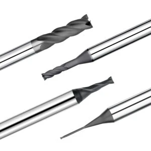
Graphite Milling Tool Wear Rate: How Graphite Density Alters Wear Mechanisms
Evaluating tool life during precision electrode milling requires tracking the full wear progression rather than asking if a tool can still cut. Machining hours alone reveal very little without inspecting the cutting edge for steady flank wear, micro-chipping, or sudden edge rounding. Connecting these wear patterns to graphite density, grain structure, and cutting forces establishes the actual graphite milling tool wear rate.
Different graphite grades produce distinct wear mechanisms depending on density and microstructural bonding. While high-density graphite increases the mechanical load on the cutting edge, particle size and porosity dictate localized friction and fracture behavior. We always identify the primary wear mechanism first, then trace the root cause back to material properties or cutting parameters.
Flank Wear and Edge Wear on Graphite End Mills
Inspecting graphite end mills requires close examination of flank wear and cutting edge integrity. Gradual, uniform flank wear is normal and results from steady abrasive contact against carbon particles over long cutting distances. Sudden edge chipping, however, points to cutting load spikes, material inconsistencies, or insufficient cutting edge strength.
Shop-floor tool checks must go beyond looking for gross breakage with the naked eye. We inspect cutting edges under a toolmaker’s microscope, comparing the worn profile against a new tool’s land width. When flank wear bands widen and part finish deteriorates, tool replacement is scheduled immediately to preserve tight graphite electrode tolerances.
Abrasive Wear Mechanisms in Graphite Milling Tools
Graphite machining generates fine, abrasive particles rather than continuous chips, creating extreme friction along the cutting edge and relief faces. Continuous contact with hard carbon particles abrades uncoated carbide tools quickly. Certain abrasive graphite grades accelerate flank wear drastically, making diamond coatings necessary to resist abrasive rubbing.
Analyzing abrasive wear requires evaluating material abrasiveness, particle grain size, and cutting edge preparation together. Higher density does not automatically guarantee faster abrasive wear, as grain uniformity plays a major role. Inspecting worn tool lands under magnification provides far more diagnostic value than basic material data sheets alone.
The Impact of Graphite Density on Cutting Edge Chipping
Machining high-density graphite often produces clean initial cuts, followed by sudden micro-chipping along the cutting edge over longer runs. This failure mode rarely stems from poor tool quality alone. Instead, it reflects the intense localized impact forces generated when fracturing dense, tightly bonded graphite matrices.
Graphite density influences edge chipping indirectly through porosity and particle bonding strength. Higher compaction increases mechanical shear resistance, subjecting fragile tool tips to higher cutting forces. When chipping occurs across different graphite grades, verifying material consistency and chip load per tooth takes priority over simply swapping tool brands.
The Relationship Between Graphite Dust and Tool Wear Rates
Dust evacuation characteristics offer immediate insight into graphite machining stability and edge condition. Clean fracturing produces predictable dust, but worn, rounded cutting edges start crushing rather than shearing the material, generating excess fine airborne dust. This sudden surge in dust volume often signals an accelerating graphite milling tool wear rate.
When dust output increases alongside rougher surface finishes and higher spindle loads, cutting edge deterioration is underway. Machinists should inspect vacuum suction, toolpath engagement, and material density immediately. Maintaining effective dust extraction prevents recutting abrasive particles, which protects the graphite milling tool wear rate and extends tool life.
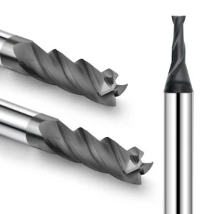
How Graphite Density Affects Graphite Milling Tool Life
Machinists often notice identical end mills from the same production batch delivering vastly different service lives across various graphite stocks. When switching graphite grades without updating feeds and speeds, tools quickly experience flank wear and micro-chipping. Rather than faulting tool quality, experienced CNC programmers inspect material density, grain size, and cutting load variations.
Graphite density serves as a reliable indicator of machining difficulty rather than a standalone metric for tool life calculation. Overall graphite milling tool life depends on grain cohesion, tool geometry, cutting parameters, and machine rigidity. Monitoring edge wear trends under real cutting conditions provides far more accurate tool life predictions than standard material datasheets.
The Relationship Between Graphite Density and Tool Life
Evaluating cutting edge conditions after a fixed cutting distance reveals how material density alters tool life. Denser graphite often increases mechanical shear resistance and abrasive grain friction, accelerating wear rates along the cutting land. However, this relationship is not strictly linear, as grain uniformity heavily influences edge stability.
Material density influences cutting forces and contact friction rather than directly determining overall tool longevity. When testing different graphite grades, we record linear cut distance, spindle load, and flank wear width under identical setups. This physical data delivers a far more accurate benchmark for graphite milling tool life than comparing machine runtime hours alone.
Why the Same Graphite End Mill Yields Different Tool Lives Across Graphite Grades
Switching graphite grades changes how the cutting edge shears the material matrix. Even if two grades share similar densities, differences in particle size, binder volume, and porosity alter localized impact forces. These microstructural shifts explain why the exact same graphite end mill can show starkly different wear rates across grades.
Premature wear rarely indicates a defective cutting tool. Machinists should track material removal rates, spindle acoustics, and cutting edge rounding before altering setups. Re-verifying chip load and radial engagement ensures predictable tool life and tight dimensional tolerances when transitioning between different graphite grades.
How High-Density Graphite Machining Affects Tool Life
High-density graphite machining increases cutting resistance, especially during heavy roughing passes with wide radial engagements. High compaction forces the cutting edge against dense carbon particles, causing thermal stress and edge rounding. Instead of simply dropping spindle speed, machinists should verify that chip load per tooth remains within the tool’s stable cutting envelope.
When high-density graphite spikes machine load, adjusting axial depth, radial step-over, and feed per tooth protects the tool. For tight-tolerance graphite electrodes, reducing material removal per pass prevents premature tool failure. Managing cutting forces early saves considerable time otherwise lost to tool offsets and manual surface polishing.
Extending Graphite Milling Tool Life Through Machining Conditions
Maximizing tool life requires optimizing the entire machining ecosystem rather than tweaking a single feed rate. CNC machinists should verify graphite density first, then establish a stable cutting window based on tool diameter, flute count, and depth of cut. Prioritizing stable chip loads over aggressive cutting speeds prevents edge chipping.
Proper dust extraction, short tool overhangs, and rigid tool holding are vital for extending graphite milling tool life. Trapped, abrasive graphite dust recuts within the flutes, accelerating abrasive flank wear. Balancing cutting parameters, toolpath strategies, and dust collection ensures maximum tool longevity and consistent surface quality.

Selecting Graphite End Mills Based on Graphite Grade
Selecting the right graphite end mill requires evaluating more than just bulk material density. In our shop, we first verify grain size, porosity, and whether the toolpath calls for aggressive roughing or high-detail finishing. Microstructural variations across graphite grades create distinct wear patterns, meaning tooling choices must match cutting loads.
CNC machinists must balance flute count, helix angle, core rigidity, and coating types against material specs. We establish a reliable machining window first, then fine-tune feeds and speeds based on physical edge wear and part finish. This practical approach ensures consistent results across demanding graphite grade machining projects.
Selecting Graphite End Mills for High-Density Graphite Machining
High-density graphite machining demands exceptional cutting edge strength and extreme wear resistance. Heavy roughing passes generate continuous mechanical cutting loads against dense carbon structures. For tight-tolerance graphite electrodes, cutting edges must stay razor-sharp to prevent dimensional drift and excessive tool deflection.
Selecting tooling for dense graphite is not just about choosing the thickest coating available. We match edge preparation to material grain size, depth of cut, and actual machine loads. If high abrasiveness causes fast flank wear, ultra-hard coatings are essential; if edge chipping dominates, stabilizing tool geometry takes priority.
Selecting Graphite End Mills for Low-Density Graphite Machining
Low-density graphite machining shifts our tooling focus toward edge sharpness and chip evacuation. Loose particle bonding and high porosity make low-density stock prone to grain pull-out, corner blowouts, and heavy airborne dust. Overly aggressive feeds can easily shatter delicate electrode ribs and thin-walled features.
When milling low-density graphite, we select sharp cutting geometries with polished flutes to shear rather than crush the material. Controlling cutting pressure prevents brittle breakout along sharp corners and fine details. Sacrificing aggressive material removal rates in favor of smooth, low-impact toolpaths delivers clean edges and superior surface finishes.
Matching Graphite Density with Graphite End Mill Geometry
Matching graphite density to tool geometry requires evaluating how material fractures during the cut. Denser grades generate finer, abrasive dust requiring rigid tool cores and ample chip clearance. We adjust flute count, relief angles, and core thickness to balance tool deflection against smooth dust evacuation.
High-density, abrasive materials benefit from reinforced cutting edges and low flute counts to handle cutting resistance. Conversely, materials prone to micro-chipping require positive rake angles for low-force cutting. Tailoring graphite end mill geometry to real-world failure modes prevents premature wear and stabilizes CNC cycle times.
Are Diamond Coated Graphite End Mills Suitable for High-Density Graphite?
Diamond-coated tools are the industry standard for high-density graphite machining due to their extreme hardness. Uncoated carbide tools rapidly develop severe flank wear from the constant abrasive action of dense carbon particles. A high-quality diamond coating dramatically extends tool life during high-volume, continuous production runs.
However, diamond coatings are not a universal fix for every machining issue. If tool breakage or part chipping stems from excessive tool overhang or machine vibration, coating hardness will not resolve the problem. We evaluate toolpath stability, tool geometry, and production batch sizes to ensure diamond coated end mills provide maximum ROI.
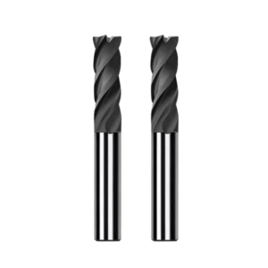
Optimizing Graphite Milling Parameters Based on Graphite Density
When transitioning between graphite grades, adjusting a single CAM variable rarely improves tool life. CNC machinists must optimize spindle speed, feed rate, radial engagement, and chip load as an interconnected system. Using existing parameters as a baseline, monitor spindle load, cutting sound, dust flow, and edge wear to lock in a stable machining window.
Never assume that high-density graphite automatically demands slow cutting speeds. Some dense grades machine smoothly, while looser structures can cause severe tool wear due to abrasive grain pull-out. Prioritizing actual cutting performance and edge wear trends over theoretical formulas ensures reliable graphite milling parameters and stable cycle times.
Matching Graphite Density with Spindle Speed
Spindle speed selection should account for material density, tool diameter, coating type, and operation stage. When cutting dense graphite, elevated spindle loads or harsh cutting acoustics warrant checking surface footage and edge prep before dropping RPM. Abrupt speed reductions often induce rubbing rather than clean shearing.
During finishing operations, spindle speed directly controls surface integrity and cutting edge stability. During roughing, it balances material removal rates with spindle load. Speed adjustments must always serve cutting stability and thermal control rather than arbitrary target numbers.
Matching Graphite Density with Feed Rate
Feed rate dictates chip load per tooth and instantaneous tool stress when switching graphite stocks. In high-density graphite machining, rapid flank wear often stems from an excessive feed per tooth overloading the cutting edge. Matching flute count to the material’s shear resistance restores cutting balance.
Underfeeding is equally destructive, as overly light chip loads cause abrasive rubbing and premature edge rounding. We calculate feed per tooth from graphite density, tool diameter, and cutting depths, then verify edge condition under magnification. Maintaining consistent chip load protects tool edges and prevents premature tool wear.
Relationship Between Graphite Density and Depth of Cut
Depth of cut significantly impacts cutting resistance in high-density graphite milling. Increasing radial step-over expands cutting edge contact, quickly spiking spindle load and mechanical deflection. During roughing passes on dense stock, reducing radial engagement while maintaining axial depth stabilizes cutting forces and edge wear.
Axial depth of cut requires equal care, especially in deep slots and narrow cavities. Accelerated wear in enclosed features usually points to poor dust evacuation or excessive tool overhang rather than material defects alone. Depth of cut must always be paired with tool rigidity and dynamic toolpath strategies.
Controlling Tool Wear Rate via Graphite Milling Parameters
Controlling tool wear requires dialing in a stable parameter window before pushing for maximum feed rates. When testing unfamiliar graphite grades, inspect cutting edge wear after a fixed cutting distance before altering parameters. This methodical baseline isolates which variable actually improves edge retention.
Track flank wear width, micro-chipping, and part surface finish after each test pass. An optimization is successful only when the tool wear rate drops without sacrificing dimensional tolerances or surface quality. Real-time wear progression remains the most reliable metric for validating cutting parameters.
Improving Graphite Milling Tool Life through Parameter Optimization
Extending graphite milling tool life requires aligning raw stock, tool geometry, and cutting parameters into a cohesive setup. If dense graphite overloads the cutter, reduce chip load per tooth; if edge chipping dominates, smooth the toolpath entry. When abrasive dust causes flank wear, improve vacuum evacuation and air assist.
Troubleshooting short tool life starts by logging material density, tooling specs, feeds, speeds, and total linear cut distance. Comparing these logs against microscope photos of worn cutting edges reveals the true failure mode. This data-driven approach resolves parameter-induced wear and maximizes graphite milling tool life.
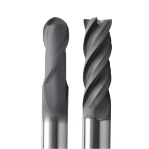
FAQ: Graphite Density and Tool Wear
Clients frequently ask about the connection between raw material density and premature tool failure. Does higher density always shorten tool life? Why do wear rates shift between graphite grades? Is diamond coating mandatory for dense stock? These challenges require balancing material microstructure, abrasive friction, cutting loads, and CAM strategies.
Avoid treating shop-floor answers as rigid rules or isolated material specs. In practice, our team evaluates grain size, porosity, tool geometry, and real wear progression under the microscope. Running standardized test cuts delivers far more actionable insight than relying on manufacturer datasheets alone.
Does graphite density affect tool wear?
Graphite density significantly impacts tool wear, but not through a simple one-to-one relationship. Changes in density alter grain structure, open porosity, and particle bonding strength. These microstructural shifts directly dictate cutting resistance, fracture behavior, and how aggressively carbon dust abrades the cutting edge.
When identical cutters show different wear rates across graphite blocks, inspect spindle loads, cut volume, and edge retention. We analyze density as one component of the complete tooling, material, and parameter ecosystem rather than judging machinability by density values alone.
Does high-density graphite wear end mills faster?
High-density graphite often subjects cutting edges to higher mechanical shear loads, which can accelerate flank wear under aggressive feeds. However, performance varies widely between grades. Particle uniformity, carbon abrasiveness, edge preparation, and radial step-over determine actual wear progression.
When milling high-density stock, measure flank wear width and edge rounding after a fixed linear distance rather than tracking machine runtime. This empirical data confirms whether rapid wear stems from material density or incorrect cutting parameters.
How does graphite density affect tool life?
We avoid predicting exact tool life hours based purely on density figures. Density acts as a baseline variable that governs mechanical cutting resistance and chip fracture dynamics. It indirectly influences tool life through cutting edge pressure and abrasive friction from fine carbon particles.
To evaluate tool life accurately across different graphite materials, run identical end mills across a fixed volume of stock. Tracking wear land growth, micro-chipping, and surface roughness provides a clear, reliable tool life benchmark for production scheduling.
What is the best end mill for high-density graphite machining?
No single end mill suits every high-density graphite application. Optimal tooling depends on material abrasiveness, grain size, cavity depth, and part tolerances. For long production runs, micro-grain carbide substrates paired with high-adhesion CVD diamond coatings provide maximum wear resistance.
If standard carbide tools dull rapidly over short cutting distances, evaluate edge geometry, flute count, and coating thickness before changing cutter diameters. Matching tool substrate and edge prep to material abrasiveness delivers immediate tool life improvements.
Does graphite grade affect graphite milling tool life?
Graphite grade dramatically affects overall tool life and requires re-validation whenever material sources change. Even at identical densities, grades vary in particle size distribution, binder composition, and manufacturing methods. These differences alter cutting edge contact dynamics and wear rates.
When switching material suppliers or graphite grades, avoid running legacy CAM programs without test cuts. Run a test pass to monitor spindle load, dust flow, part finish, and edge integrity, then dial in an optimized cutting window.
How can I reduce graphite milling tool wear rate?
Lowering tool wear requires optimizing the whole setup rather than tweaking a single feed rate. Verify material density, then check tool overhang, radial step-over, chip load per tooth, and vacuum extraction. If heavy cutting loads cause wear, reduce engagement; if abrasive friction dominates, upgrade to diamond tooling.
To systematically lower your graphite milling tool wear rate, photograph the cutting edge after a fixed machining distance and adjust parameters one at a time. This methodical troubleshooting isolates whether material properties, tooling geometry, or cutting conditions drive edge breakdown.






