


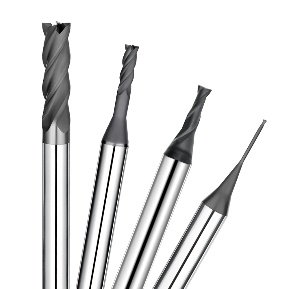
We recently consulted for a client manufacturing precision graphite electrodes. They used the same CNC setup and cutting tools to machine two graphite grades with identical nominal hardness. The results were night and day: the first material machined cleanly with predictable wear, while the second triggered severe edge chipping, heavy dust generation, and accelerated cutting tool wear that quickly destroyed tool life.
This is a recurring challenge across high-precision machine shops. When identical speeds, feeds, and end mills produce drastically different results, the root cause rarely lies in the tool path alone. Instead, graphite grain size and internal microstructure govern how the workpiece fractures, sheds chips, and interacts with the cutting edge under mechanical load.
Material cross-sections confirm that grain size, binder distribution, and internal porosity dictate the brittle fracture mechanics during milling. Coarser grains promote micro-cracking ahead of the cutting edge, which drastically impacts cutting forces, graphite milling surface finish, and edge retention. Consequently, graphite grades with identical hardness ratings will behave completely differently in real-world machining.
These structural differences explain why finishing operations often suffer from edge chipping and poor surface integrity. Fine-grained graphite yields cleaner sheared edges and tighter tolerances, whereas coarse-grained variants generate abrasive debris that scours tool flutes. Controlling graphite machining chipping requires matching the workpiece’s grain distribution to the appropriate tool geometry and relief angles.
Tool selection must always begin with the specific graphite grade and average grain size rather than nominal hardness. Materials with varied grain boundaries demand tailored feed rates, flute counts, and specialized coatings. For prolonged cycles in abrasive grades, applying a diamond coating for graphite machining is essential to resist abrasive rubbing and extend tool life.
Evaluating graphite grain size upfront prevents costly trial and error on the shop floor. The following technical breakdown explores how graphite microstructure drives chip formation, cutting forces, tool wear mechanisms, and dust management across both roughing and finishing operations.
Graphite Grain Size and Machining Mechanism: How Grain Size Alters the Cutting Process
Graphite grades with identical bulk hardness and density can behave entirely differently on the shop floor. Instead of immediately adjusting spindle speeds or feeds, experienced machinists evaluate material microstructure first. Material removal in graphite relies on localized brittle micro-fracture combined with mechanical cutting, where graphite grain size directly dictates chip morphology and cutting resistance.
Precision electrode machining reveals these material differences quickly, especially along thin ribs and deep cavities. When internal particle bonds vary, applying identical cutting parameters often triggers sudden edge breakout and inconsistent surface roughness. Understanding the fundamental graphite machining mechanism helps engineers choose proper cutting geometry instead of relying on generic parameters.
How Graphite Grain Size Affects Microstructure and Fracture Behavior
Cutting loads concentrate extreme mechanical stress at the tool edge. When local shear stress exceeds grain cohesion, micro-cracks propagate along grain boundaries rather than following the programmed toolpath. Grain size determines crack paths and particle detachment scale, directly influencing whether part edges remain crisp or suffer from severe edge chipping under identical cutting conditions.
Machining high-detail electrodes requires inspecting finished edges under magnification rather than relying solely on CMM dimensions. Observing localized spalling and surface granularity reveals how the graphite microstructure responds to cutting forces. If micro-cracking propagates uncontrollably during final finishing passes, structural integrity fails even when the cutting tool shows minimal physical wear.
Differences in Machining Behavior Between Fine-Grain and Coarse-Grain Graphite
The choice between fine-grain and coarse-grain stock involves chip formation mechanics rather than basic machinability. Fine-grain graphite provides a dense particle matrix that fractures predictably, making it essential for thin ribs and sharp corners. Coarse-grain graphite produces larger cleavage debris, which increases the risk of breakout along unsupported corners and intricate wall profiles.
Machinists should not select speeds and feeds based on grain diameter alone. Bulk density, flexural strength, and tool sharpness all interact to shape the final graphite machining behavior. When tools begin to dull on coarse grades, cutting pressure quickly pulls out large particle clusters, causing severe pitting and out-of-spec surface finishes.
Graphite Grain Boundaries, Porosity, and Machining Behavior
Graphite grains do not form solid, continuous matrices; grain boundaries and micro-pores continuously alter structural support at the cutting interface. As cutting edges enter porous regions, sudden changes in mechanical support trigger particle pullout and erratic dust formation. Analyzing the graphite grain boundary network explains why certain batches produce abnormal surface roughness during high-speed finishing.
Relying solely on average particle ratings overlooks localized porosity variations that cause inconsistent tool performance. In our CNC operations, we evaluate pore distribution, material density, and fracture dynamics together to optimize cutting strategies. For tight-tolerance electrodes and micro-milling applications, microstructural analysis delivers better process stability than merely tweaking spindle RPM.
The Impact of Graphite Grain Size on Machining Behavior: How Cutting Performance Changes
Switching raw graphite stock often alters cutting dynamics even when machine setups, feeds, and end mills remain identical. Experienced machinists track spindle load, vibration harmonics, dust texture, and edge integrity rather than focusing solely on final CMM dimensions. These real-time sensory cues directly reveal how material properties govern graphite machining behavior.
When parts show sudden dimensional drift or rough finishes across different batches, avoid randomly tweaking feed rates. Checking grain diameter, bulk density, and porosity explains the mechanical shift occurring at the tool tip. Internal particle matrices dictate cutting stability, dust formation, and edge breakout under varying chip loads.
The Impact of Graphite Grain Size on Cutting Force and Stability
Evaluating cutting forces in graphite requires monitoring real-time spindle load and tool harmonics rather than relying on theoretical metal-cutting formulas. Fine-particle stock yields smooth, predictable tool engagement with minimal chatter. Switching to larger particle stock often introduces sharp load spikes, increased acoustic noise, and micro-vibrations, proving that graphite grain size dictates baseline cutting stability.
Coarser structures do not automatically produce higher average cutting forces, but they cause severe localized load spikes. Irregular particle pullout and void intersections create dynamic shock loads on fragile cutting edges. Controlling these intermittent micro-impacts protects delicate electrode ribs far better than simply throttling back programmed feeds.
The Influence of Graphite Grain Size on Graphite Machining Chipping
Attributing part breakout strictly to dull cutting edges overlooks internal fracture mechanics. When high cutting pressure concentrates along weak grain boundaries, cracks propagate ahead of the toolpath, causing severe graphite machining chipping. This localized cleavage often dislodges large particle clusters, ruining crisp edges and thin features.
Addressing edge chipping on fine details requires balancing tool edge radius, grain structure, and localized chip loads. Dropping feed rates excessively increases abrasive rubbing and tool flank wear without preventing breakout. Matching toolpath stepovers to the material’s fracture behavior stabilizes structural integrity on high-precision electrodes.
The Impact of Graphite Grain Size on Graphite Milling Dust Generation
Variations in airborne debris volume reflect fundamental material removal mechanics rather than tooling defects alone. Brittle fracture and particle fragmentation generate distinct dust profiles ranging from microscopic flour to gritty particles. Analyzing the texture and volume of graphite milling dust provides clear feedback on whether the material is cutting cleanly or micro-spalling.
Optimizing dust extraction requires evaluating particle morphology alongside spindle speeds and vacuum flow rates. High-speed finishing passes generate ultra-fine, abrasive dust that quickly accelerates flank wear if not evacuated immediately from the cut zone. Effective dust extraction protects machine guideways while extending overall end mill life.
Machinability Differences Between Fine-Grain and Coarse-Grain Graphite
Assessing fine-grain versus coarse-grain graphite centers on process predictability rather than raw cutting speed. Fine-grain grades provide uniform chip release and structural support, making them the standard for intricate features and razor-thin walls. Coarse-grain graphite offers cost savings for bulk roughing but requires wider tolerances to accommodate localized edge breakout.
True machinability represents a composite balance of edge retention, tool wear, and surface finish. Shop engineers evaluate porosity, flexural strength, and grain cohesion together before finalizing cutting parameters. Correlating internal material microstructure with actual shop-floor cutting dynamics ensures repeatable results across all electrode production runs.

Graphite Grain Size and Graphite Milling Tool Wear: How Grain Size Affects Tool Wear
A production run can run smoothly on solid carbide end mills until a material change suddenly causes rapid edge rounding, severe pitting, and chipping. Microscopic tool inspection usually reveals that premature failure is rarely just about cutting time. Instead, internal material structure directly controls how abrasive debris interacts with the cutting edge during continuous passes.
Accurately diagnosing graphite milling tool wear requires evaluating the interaction among raw stock, tool geometry, and cutting parameters. As internal particle bonds fracture, abrasive debris rubs against tool flanks while uneven cleavage creates micro-impact loads. When tool life drops without warning, evaluating raw material consistency prevents misdiagnosing the problem as a defective tool batch.
The Impact of Graphite Grain Size on Graphite Milling Tool Wear
Examining worn graphite cutters under magnification reveals distinct patterns of flank wear, micro-chipping, and edge rounding. Coarser internal particles generate larger fracture debris that exerts severe localized shock loads on sharp tool edges. This dynamic confirms that graphite grain size plays a fundamental role in accelerating abrasive wear mechanisms during milling passes.
When wear concentrates on a specific graphite batch, compare performance against baseline material under identical feed rates and stepovers. Machinists should track cut distance, spindle load, and flank wear land growth rather than relying on total in-cut hours. This data-driven approach isolates whether abrasive tool degradation stems from material variations or incorrect cutting speeds.
The Relationship Between Graphite Grain Size and Tool Life
Tracking cutter longevity solely by operating hours masks the underlying wear mechanics of brittle non-metals. Identical diamond-coated cutters running the same toolpaths can deliver vastly different service lives depending on raw particle consistency. While fine-grained stock ensures steady tool engagement, sudden structural shifts can cut graphite tool life in half due to aggressive abrasive friction.
To maximize cutter durability across production runs, track tool life by total linear cut length or completed electrode counts. Logging graphite grades alongside wear patterns helps identify problematic, highly abrasive batches before they damage delicate workpieces. Establishing clear empirical wear trends prevents unnecessary and costly changes to proven CNC machining programs.
Why Coarse-Grained Graphite Can Exacerbate Tool Wear
Machining coarse-grained grades subjects tool cutting edges to intermittent micro-impacts rather than smooth, continuous chip shearing. The irregular cleavage of large particle clusters creates dynamic shock loads that quickly chip unreinforced carbide edges. Furthermore, released particles act like loose grinding media in the cut zone, accelerating abrasive graphite cutting tool wear.
Switching to premium tooling without fixing fundamental cutting conditions rarely solves premature edge degradation. Operators must first verify tool overhang, depth of cut, and high-volume vacuum evacuation to clear abrasive dust instantly. Matching edge prep, chip load, and dust extraction to coarse structures stabilizes tool life far more effectively than guesswork.
The Combined Impact of Graphite Grain Size, Cutting Conditions, and Tool Wear
The mechanical influence of grain diameter magnifies as cutting parameters become more aggressive. A specific grade may cut cleanly during light finishing passes but trigger severe abrasive wear once axial depth or feed per tooth increases. Analyzing the grain size effect on graphite machining alongside cutting parameters reveals the exact threshold where mechanical tool degradation accelerates.
When troubleshooting sudden tool failure, change only one cutting parameter at a time while holding the tool and material constant. Monitor spindle load, flank wear progression, and workpiece surface finish after each test pass to pinpoint root causes. This systematic testing protocol isolates whether wear is driven by cutting parameters, tool substrate, or raw material variations.
The Impact of Graphite Grain Size on Milling Surface Finish
Graphite electrodes often pass dimensional CMM inspection but get rejected by clients for unacceptable surface texture. Running identical CNC programs and tooling on different graphite batches frequently yields inconsistent results, ranging from smooth finishes to dull, granular surfaces with micro-pitting. This variation confirms that graphite grain size dictates how particles detach during final finishing passes.
Solving surface defects on high-precision electrodes involves more than simply dropping the feed rate. Machinists must evaluate edge sharpness, material density, depth of cut, and tool engagement angle. When surface roughness shifts between stock batches, inspecting the material’s internal particle matrix is the first step to diagnosing the problem accurately.
How Fine-Grain Graphite Affects Milling Surface Finish
Fine-grain graphite excels in detailed electrode fabrication, thin-wall milling, and sharp cavity features. Its dense particle matrix provides uniform fracture behavior under sharp cutting edges, creating crisp details and a refined surface texture. However, achieving a superior graphite milling surface finish still requires optimized chip loads, high-grade diamond tooling, and minimal dynamic spindle runout.
Validating fine-grain material quality requires inspecting both the cutting tool edge and the machined surface under magnification. Measuring profilometer values alongside visual surface topography isolates whether finish degradation stems from raw material porosity or subtle cutting edge breakdown. This rigorous approach ensures consistent finish quality across multi-cavity EDM tooling runs.
Coarse-Grain Graphite and Surface Roughness
Coarse-grain graphite presents significant finishing challenges due to larger internal particle clusters that easily pull out during cutting. These dislodged particles leave behind microscopic voids and localized pits that degrade aesthetic quality and performance. If finishing stock allowances are too thin or tools show slight flank wear, poor graphite surface roughness quickly ruins part specifications.
When surface quality drops on coarse grades, verify cutter sharpness and stepover engagement before changing feeds and speeds. Reducing feed rates excessively causes tool rubbing and compression rather than clean particle fracture, accelerating cutter dulling without improving surface texture. Maintaining a positive, sharp cutting action remains vital for coarse-grained stock.
The Relationship Between Graphite Grain Size, Chipping, and Surface Finish
Surface finish quality and edge integrity are closely linked during graphite finishing passes. Localized micro-fractures not only cause surface pitting across floor faces but also trigger breakout along delicate ribs and thin ribs. Managing graphite machining chipping requires controlling crack propagation along grain boundaries during both continuous cuts and critical tool entry-exit paths.
When localized edge notches appear on otherwise acceptable parts, check for stress concentrations at sharp corner transitions. Prioritize rigid toolholding, low cutting pressure, and fresh cutting edges before altering axial depths of cut. On tight-tolerance EDM electrodes, preventing localized chipping is critical because a single fractured rib can scrap the entire part.
Optimizing Surface Finish Based on Graphite Grain Size
Optimizing surface finish requires tailoring cutting strategies to specific graphite grades rather than relying on one-size-fits-all parameters. Classifying the raw stock as ultra-fine, fine, or medium-coarse helps establish baseline radial stepovers and finishing stock allowances. Incremental parameter adjustments then dial in the best match between material fracture mechanics and toolpath motion.
Long-term machining success depends on treating the grain size effect on graphite machining as a primary baseline variable. Creating dedicated feeds and speeds for specific grain classifications ensures consistent surface finishes across production batches. This systematic approach stabilizes cutting results, maximizes tool life, and eliminates costly scrap on precision graphite electrodes.
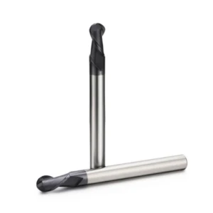
Graphite Grain Size and Machining Tools: Selecting the Right Tool for Different Graphite Grades
Switching raw stock on identical CNC setups can quickly cut tool life and degrade finished surfaces. Transitioning from fine-grain to coarse-grain graphite changes how abrasive particles interact with the cutting edge, shifting localized impact loads significantly. Experienced machinists re-evaluate edge prep, core thickness, flute capacity, and dynamic cutting pressure whenever material grades change.
Selecting effective graphite machining cutting tools requires evaluating raw particle size alongside tool diameter and flute count. Factors like thin-wall geometry, stock allowances, surface finish targets, and tool stickout must all align. Accounting for material microstructure ensures an optimal balance between edge retention, part integrity, and extended tool life.
Selecting Tools for Fine-Grained Graphite
Machining fine-grain graphite for micro-slots, narrow ribs, and intricate electrode contours demands sharp cutting edges and high dimensional stability. Because fine-particle grades fracture cleanly, success relies on controlled, low-pressure cutting action rather than aggressive material removal rates. Precision geometries on specialized graphite machining cutting tools prevent localized corner breakage on delicate electrode ribs.
Light chip loads during finishing passes protect micro-features while minimizing premature cutting edge dulling. For long-running production, hard-coated end mills provide the abrasion resistance needed to maintain tight tolerances across multi-hour cycles. Matching tool specifications to total cut length and accuracy requirements keeps overall tooling costs under control.
Selecting Cutting Tools for Coarse-Grain Graphite
Coarse-grain graphite machining prioritizes edge strength and dynamic shock resistance over razor-sharp cutting geometry. Dislodging large particle clusters creates continuous micro-impacts on the tool tip, making fragile edges prone to chipping. Choosing end mills with reinforced edge hone balances shearing action with structural support to handle unstable fracture dynamics.
For large electrodes with heavy roughing stock, prioritize core rigidity, ample gullet clearance, and abrasive wear resistance. Always swap out worn roughers before starting finishing passes to prevent edge breakout on brittle workpieces. Stable graphite cutting tools prevent dull cutting edges from pulling out large grains and destroying surface accuracy.
Matching Graphite Grain Size with End Mill Geometry
Tool geometry must adapt directly to the fracture mechanics of the specific graphite stock. Because graphite grain size dictates how particles break away, machinists must carefully select core diameter, relief angles, flute depth, and tool overhang. Excessive tool extension inside deep cavities introduces deflection and chatter, causing edge chipping even in soft graphite grades.
Separate tool geometry choices for roughing and finishing passes on high-tolerance electrodes. Roughing operations require maximum core diameter and stiffness, while finishing passes depend on precise edge radii and minimal dynamic runout. If surface roughness lags behind dimensional accuracy after a tool change, inspect tool runout and edge geometry first.
Matching Graphite Grain Size with Flute Design and Helix Angle
Graphite removal generates fine, abrasive dust rather than continuous metal ribbons, requiring dedicated flute profiles. Flute gullet design governs dust evacuation from the cut zone, while the helix angle alters the balance between radial and axial cutting forces. Adjusting these parameters according to the grain size effect on graphite machining prevents dust packing and reduces cutting temperatures.
Deep slotting in coarse grades requires 2-flute or 3-flute end mills with wide gullets to clear heavy dust volume efficiently. Conversely, finishing fragile ribs benefits from moderate helix angles and 4-flute designs to stabilize axial tool forces and prevent edge breakout. Tailoring flute geometry to grain characteristics ensures repeatable tool life and consistent surface finishes.
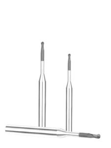
Diamond Coating for Graphite Machining: How Grain Size Influences Tool Coating Selection
Uncoated solid carbide end mills often perform well during initial test passes on graphite, but edge degradation accelerates rapidly as parts accumulate. Abrasive carbon dust continuously rubs the cutting zone, dulling sharp cutting edges, increasing surface roughness, and causing critical dimensions to drift. Microscopic edge inspection proves that internal material abrasiveness and particle bonding dictate tool flank wear rates.
Specifying a proper diamond coating for graphite machining requires analyzing raw material grain size, bulk density, cycle times, and tolerance limits together. While diamond layers significantly slow cutting edge wear, they cannot compensate for incorrect edge prep or poor feeds and speeds. Achieving reliable tool life depends on matching diamond layer properties to the specific graphite grade.
Why Diamond Coating for Graphite Machining Suits Highly Abrasive Graphite
Graphite does not form continuous metallic chips; it breaks into microscopic, highly abrasive particles that act like grinding compound on bare carbide. During extended high-speed milling, edge rounding alters cutting forces and leads to localized workpiece breakout. Applying a diamond coating for graphite machining provides exceptional surface hardness, preventing flank wear and stabilizing cutting edge geometry over long runs.
Uncoated carbide may handle low-volume roughing, but high-density grades and long-run electrode jobs demand high-adhesion diamond films. Shop engineers evaluate total linear cut distance, edge wear progression, and cost-per-part before selecting tool coatings. Investing in diamond-coated tooling delivers lower overall machining costs by preventing scrap and eliminating mid-program tool changes.
The Relationship Between Graphite Grain Size and Tool Life
Raw particle size directly dictates how abrasive dust fractures and interacts with cutter surfaces. While fine-particle stock creates continuous micro-abrasion across the flank face, coarser grades produce larger debris that exerts micro-impacts alongside abrasive wear. Tracking linear cut distance and flank wear progression provides a reliable baseline for predicting overall graphite tool life.
When switching to a new graphite supplier or different grain classification, never rely on previous tool life estimates. Running small-batch verification cuts under identical feeds and speeds reveals genuine wear trends before full production begins. Maximizing diamond-coated tool longevity preserves tight electrode tolerances, reduces machine downtime, and ensures repeatable shop-floor productivity.
Diamond Coating Requirements for Fine-Grain vs Coarse-Grain Graphite
Selecting coating thickness and adhesion depends heavily on the mechanical contrast between fine grain and coarse grain graphite. Fine-grain stock requires razor-sharp cutting edges and smooth, nanocrystalline diamond coatings to prevent localized chipping on delicate ribs. Coarse-grain stock demands tough, microcrystalline diamond coatings with exceptional film adhesion to withstand continuous micro-impact shock loads.
Documenting specific tool wear patterns under magnification reveals whether failure stems from smooth abrasive polishing or coating delamination. If coarse particles chip cutting edges, simply increasing diamond thickness without improving edge prep or core rigidity will fail. Matching substrate geometry, coating morphology, and grain characteristics creates a balanced cutting tool assembly.
How Diamond Coating Reduces Graphite Milling Tool Wear
The primary function of diamond films is providing a hard barrier against extreme abrasive friction at the cutting interface. Without coating protection, bare carbide rapidly loses its sharp cutting profile, causing cutting loads to spike and surface finishes to degrade. Applying the correct diamond grade slows down graphite milling tool wear, ensuring consistent surface quality across extended runs.
Even the highest-grade diamond coating cannot overcome severe spindle runout, excessive tool stickout, or poor dust extraction. Re-cutting trapped, abrasive dust accelerates diamond layer breakdown regardless of coating quality. Maximizing tool life requires treating diamond coatings as one part of a balanced machining system alongside rigid setups and optimized cutting parameters.

Graphite Grain Size Optimization Strategy: From Tool Wear to Machining Quality
The impact of raw particle structure extends across the entire CNC process, altering cutting resistance, tool degradation, edge breakout, and surface roughness. When troubleshooting production bottlenecks on graphite electrodes, experienced engineers avoid random adjustments. Instead, we analyze raw material structure, tooling specifications, and cutting dynamics as an integrated system.
When standard CNC programs produce inconsistent results across different stock batches, log the material density, porosity, and grain classification first. Use systematic, single-variable testing rather than altering speeds, feeds, and end mills simultaneously. This structured approach quickly reveals whether poor performance stems from raw stock variability or mismatched cutting parameters.
Adjusting Graphite Machining Parameters Based on Grain Size
Establishing optimized feeds and speeds requires matching cutting loads to the fracture mechanics of the specific graphite grade. Fine-grain grades tolerate higher surface speeds and shallower depths of cut to achieve flawless surface finishes on intricate ribs. When running a new graphite grade, begin with conservative graphite machining parameters while keeping tool geometry and setups constant.
Adjust only one cutting variable at a time while logging spindle load, acoustic harmonics, dust morphology, and flank wear progression. If reducing feed per tooth prevents corner breakout but accelerates abrasive rubbing, re-evaluate tool edge hone and minimum chip thickness. Establishing a stable machining window delivers long-term process repeatability across high-volume production runs.
Optimizing Graphite Tool Life Based on Grain Size
Evaluating cutter longevity requires tracking total linear cut length and finished part counts rather than machine-on hours. Structural shifts between fine and coarse grades alter how abrasive particles fracture and slide across the tool edge. When edge failure occurs unexpectedly, inspect cutting edges under magnification to classify flank wear, micro-chipping, or coating delamination.
Process optimization focuses on balancing cutting geometry with material abrasiveness rather than blindly buying expensive end mills. For long-cycle electrodes, high-adhesion diamond films stabilize wear rates and reduce tool change frequency. Consistent graphite tool life ensures repeatable tolerances and lowers overall manufacturing costs per part.
Reducing Graphite Machining Chipping through Proper Tool Selection
Solving edge breakout requires pinpointing the exact failure location—such as thin walls, sharp outside corners, or lead-in points. Inspect tool runout, gauge length, edge preparation, and finish stock allowances before modifying programmed feeds. Rigid toolholding combined with dedicated graphite machining cutting tools prevents deflection and dynamic chatter on delicate electrode features.
Tool selection must match both the workpiece geometry and the material’s fracture characteristics. Heavy roughing passes demand maximum core thickness and flute volume, while fine finishing passes require razor-sharp edges with minimal runout. When coarse structures exhibit severe micro-fracture, optimizing toolpaths and entry strategies prevents edge chipping far better than dropping feed rates.
Improving Graphite Milling Surface Finish and Dust Control through Tool and Parameter Matching
Surface finish quality and dust evacuation are directly connected during high-speed graphite milling passes. Trapped abrasive particles re-enter the cut zone, accelerating flank wear and causing severe micro-pitting on part floors. Achieving a uniform graphite milling surface finish requires tracking profilometer values, surface texture, and dust extraction efficiency simultaneously.
Maintain high-velocity vacuum airflow right at the cutter interface to clear abrasive dust instantly. Adjust radial stepovers and finishing stock allowances to match the specific grain diameter once tool runout is verified. Combining sharp diamond tooling, rigid machine setups, and proper dust extraction ensures consistent, mirror-like electrode surfaces.

FAQ: The Effect of Graphite Grain Size on Machining
Machinists often ask why proven cutting parameters and toolpaths suddenly fail when switching to a different graphite stock. Evaluating raw material density, porosity, fracture mechanics, and abrasive wear patterns reveals how graphite grain size alters cutting dynamics. Microstructural variations directly impact machining stability across different production batches.
If your shop experiences sudden drops in tool life, rougher surface finishes, corner breakout, or excessive airborne dust, use this troubleshooting guide. Cross-referencing raw particle specifications with real-time spindle load and tool wear helps pinpoint the root cause of machining failures.
How does graphite grain size affect machining?
Raw particle diameter directly dictates chip formation mechanics, cutting resistance, and fracture behavior at the cutting edge. Brittle micro-fracture governs material removal, meaning variations in internal grain cohesion alter localized cutting loads and edge retention on fine features. Understanding the grain size effect on graphite machining ensures predictable milling results.
When identical parameters produce erratic results on new stock, check raw grain size, bulk density, and porosity. Monitoring acoustic harmonics, spindle load fluctuations, and finished edge integrity reveals whether the internal particle structure is destabilizing the cutting process.
Does graphite grain size affect graphite tool life?
Raw particle structure significantly impacts cutter longevity, though it works in combination with material abrasiveness and cutting parameters. Large, irregular particles create intermittent micro-impact shock loads, while fine, dense particles generate continuous abrasive friction. These combined forces directly dictate overall graphite tool life during high-speed milling.
To accurately track cutter wear across different graphite grades, measure total linear cut distance and flank wear land growth rather than machine operating hours. This data-driven approach isolates whether premature edge dulling stems from material variations or incorrect cutting speeds.
Does grain size affect graphite milling surface finish?
Internal particle dimensions govern how chips cleave away from the workpiece during light finishing passes. Coarser particles can pull out unevenly, leaving microscopic voids and pits on cavity floors, while fine-grained grades yield dense, uniform textures. Achieving an optimal graphite milling surface finish requires matching stock allowances to raw grain size.
If surface roughness deteriorates unexpectedly, inspect cutter runout, cutting edge sharpness, and finish stock stepovers simultaneously. Comparing profilometer Ra values against microscopic surface images isolates whether poor finish quality stems from material porosity or tool flank wear.
Does coarse-grain graphite cause more chipping and tool wear?
Coarser grades are naturally more prone to localized micro-fracture along unsupported corners and thin ribs. However, coarse particle structure alone does not guarantee edge failure; high cutting pressure, dull cutting edges, and tool deflection are often the true triggers behind severe graphite machining chipping.
When milling coarse grades with thin ribs or sharp outside corners, prioritize rigid setups and low-pressure finishing toolpaths. Inspect cutting edges under magnification to ensure micro-chipping on the tool tip is not fracturing the workpiece edges.
Is diamond coating better for coarse-grain graphite machining?
Diamond coatings provide extreme surface hardness to combat abrasive carbon dust during high-volume production runs. However, applying a diamond coating for graphite machining cannot fix problems caused by excessive tool overhang, dynamic runout, or incorrect edge preparation on coarse grades.
Selecting diamond-coated end mills requires evaluating total production volume, material abrasiveness, and electrode tolerance limits. While uncoated carbide handles short prototyping runs, premium diamond coatings lower overall manufacturing costs on long-running, abrasive production jobs.
How does graphite grain size affect graphite milling dust?
Raw particle dimensions and binder cohesion determine whether cutting debris fractures into gritty chips or microscopic airborne powder. While grain structure shapes debris morphology, the total volume of graphite milling dust is also driven by tool sharpness, cutting speeds, and chip loads.
Troubleshooting heavy dust accumulation begins with inspecting particle texture, tool flank wear, and vacuum extraction placement. Clearing abrasive dust instantly from the cut zone prevents re-cutting debris, which protects machine guideways and significantly extends tool life.






