When performing the final finishing pass on high-hardness mold steel (HRC60+), the most vexing challenge is rarely the inability to cut the material. Instead, it is that persistent “matte finish”—a hazy surface layer that simply refuses to disappear.
Last month, a long-standing German client in the medical device sector sent us a familiar complaint. While machining high-precision molds (HRC63), they used what were marketed as the “best-in-class” HRC65 milling cutter bits. Despite the premium price, the side-wall finish consistently failed to meet specs. Under magnification, we detected a microscopic layer of heat-induced material degradation. This wasn’t just an aesthetic flaw; it doubled the time required for manual polishing and pushed several workpieces out of dimensional tolerance.
This scenario recurs repeatedly in our China milling cutter bits factory lab. As a fellow professional, you know that a true mirror finish isn’t solved by just cranking up the RPM. It requires a precise symphony of factors: cutting edge micro-geometry, the friction coefficient of the coating, and—most critically—radial runout control of the end mill cutter bit under extreme pressure.
Our analysis of thousands of datasets shows that many engineers overlook the balance between “edge honing” and the polishing of the flute channels. If the flutes on your HRC65 milling cutter bits aren’t smooth enough, microscopic chips will be trapped by centrifugal force. These chips then cause secondary scratching, ruining the mirror surface you just created.
I won’t dwell on textbook theories here. Drawing from 15 years of floor experience, I want to discuss practical strategies: optimizing step-overs, fine-tuning runout, and using proprietary nano-coatings to ensure your end mill cutter bits deliver a mirror finish even under heavy loads.
Be honest: on your quest for the ultimate finish, have you ever ruined a high-value mold during that final, minuscule 0.01mm pass?
Why Do Most People Fail to Achieve a Mirror Finish with HRC65 Milling Cutter Bits?
While providing technical support in North America and Europe, we frequently hear: “Why does the surface still look gray and dull despite using expensive tools?” The essence of a mirror finish is the regular reflection of light. When using HRC65 milling cutter bits on hardened steel, any microscopic inconsistency in the edge—or a dynamic balance shift of just a few microns—creates “chatter marks.” These ripples scatter light. No matter how high your spindle speed, you get an “industrial texture,” not a mirror.
Cutting heat is the other underestimated culprit. If the tool’s geometry fails to dissipate heat rapidly, localized high temperatures induce a phase transformation, creating a brittle “white layer.” We often see shops use the same cooling strategies for finishing as they do for roughing. This is counterproductive. True mirror finishes rely on precise Minimum Quantity Lubrication (MQL) or specific-frequency dry cutting to keep the cutting edge physically stable.
Case Study: Resolving Micro-Tearing on High-Hardness Steel (Over 60 HRC)
Last year, a North American mold maker machining HRC62 tool steel reported pinprick-like pits—classic microscopic tearing. The root cause was a mismatch between cutting speed and feed rate. When the radial depth of cut (step-over) for your milling cutter bits metal applications is too conservative, the tool tip doesn’t cut the metal; it rubs it. This friction exceeds the material’s yield strength, violently tearing the metal matrix away and creating those pits.
We advised them to increase the feed per tooth by 15% and optimize the helix angle compensation. The rationale is simple: we wanted the chips to detach rapidly upon formation. This minimized secondary extrusion on the finished surface. Within hours, the dull surface regained its metallic luster. Resolving tearing isn’t about reducing speed; it’s about mastering the material’s plastic deformation point.
Pitfall Guide: Not All “HRC65” End Mill Cutter Bits Are for Finishing
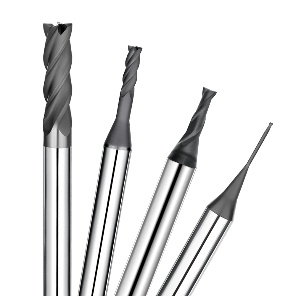
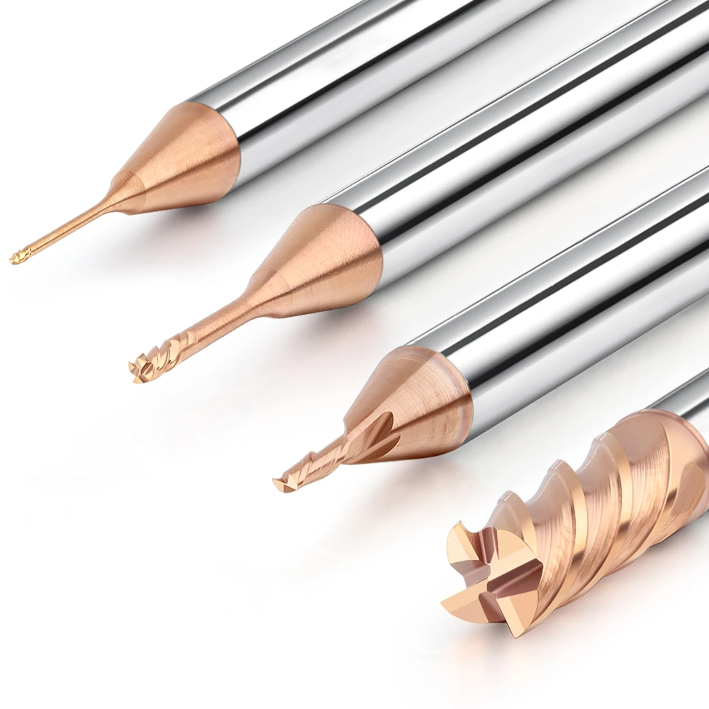
We must be candid: the performance of tools labeled “HRC65” varies drastically. Many inexpensive end mill cutter bits use a high-hardness substrate but fail the rigorous edge-finishing standards needed for precision work. Under a microscope, many of these tools show saw-toothed defects right out of the box. They are fine for roughing or pocketing, but they will never deliver a mirror finish. Those serrations will simply be imprinted onto your workpiece.
Another pitfall is coating roughness. Some low-end China milling cutter bits factories skip the essential post-coating polishing. This leaves a surface as coarse as sandpaper, which increases friction and induces BUE. A qualified finishing tool must have a substrate that meets hardness standards AND a cutting edge that has undergone fine honing after coating. Identifying these invisible manufacturing details is the only way to avoid procurement traps that look like a bargain but result in high wear and wasted material.

Three Critical Metrics for Mirror Finishes: How Our China Milling Cutter Bits Factory Controls Precision
On the factory floor, we often say: “Precision is achieved through grinding but verified through inspection.” To ensure a workpiece reaches mirror-like reflectivity, geometric consistency is the first hurdle. Through extensive trials, we discovered that—beyond standard runout—core thickness symmetry and bottom-edge flatness are the “hidden” metrics. If the grinding wheel isn’t dressed frequently—even a tiny 2μm deviation—it creates periodic vibrations at high speeds, destroying the surface flatness you’re working to achieve.
To lock down these variables, we use a closed-loop system from raw material to final inspection. For our high-end China milling cutter bits factory series, we don’t just check carbide grain uniformity; we use high-magnification confocal microscopy to perform 3D reconstructions of the edge trajectory after secondary gashing. For B2B clients, this consistency isn’t just a “nice-to-have”—it translates to an 80% reduction in machine compensation and setup time.
The Impact of Edge Roughness on the Service Life of Metal Milling Cutter Bits
Many peers think a finishing tool just needs to be “sharp.” However, our feedback on metal milling cutter bits shows that if an edge is too sharp without controlled honing, it acts like a jagged saw blade. The moment it hits hardened steel, those microscopic peaks fracture. This “initial wear” triggers a vicious cycle of fluctuating cutting forces. That hazy, dull look on a “finished” surface is often the result of microscopic tool failure caused by excessive edge roughness.
We use controlled edge-rounding technology to keep roughness within an extremely tight tolerance. This ensures the edge is as smooth as a surgeon’s scalpel but tough enough to resist chipping. This treatment reduces friction-induced heat and optimizes stress distribution, extending tool life by over 30%. Only a nanoscale smooth edge can shear away ultra-thin chips without disrupting the material’s underlying grain structure.
Coating Smoothness: Why S-AlTiN or Nano-Si Coatings Excel in High-End Milling
In high-end manufacturing, a coating is more than a wear layer—it is a “self-lubricating skin.” Standard tools often have “droplets” (micro-particles) after PVD coating that act like sandpaper. If you use an end mill cutter bit in this condition, those hard particles will gouge microscopic grooves into your workpiece. This is why we recommend Nano-Si coatings. They provide exceptional “red hardness” while maintaining a very low friction coefficient.
This technology balances oxidation resistance with surface smoothness. When machining materials over HRC60, Nano-Si coatings form a dense protective film that prevents chips from chemically adhering to the tool. In a study for an optical mold client, using this surface-smoothing treatment dropped the Ra (roughness) value by a full order of magnitude. This isn’t luck; it’s the result of meticulous control over droplet density and film stress.
Practical Parameters: Mirror-Finish Strategies for HRC65 Milling Cutter Bits
Even experienced machinists often fall into “habitual thinking,” believing a mirror finish is just about leaving a small finishing stock. However, our lab data shows that HRC65 milling cutter bits depend heavily on “cutting force stability.” If parameters are off, the tool squeezes rather than cuts the metal. This leads to work hardening, turning a lustrous finish into a dull, lackluster one.
We recommend a “staged parameter reduction” strategy. Higher cutting speeds (Vc) are not always better. Excessive RPM can induce high-frequency chatter. By moderately reducing the spindle speed by 10% at critical points, the tool achieves a more stable cut. Your programming logic must resonate with the tool’s physical limits. Only then can you achieve that glassy, still-water reflection.
Why We Keep the Radial Depth of Cut (Ae) Below 0.05mm
We frequently advise clients against removing too much material during the final pass. The Ae directly dictates the path of cutting heat. Once Ae exceeds 0.05mm, resistance increases exponentially, causing minute tool deflection. This is catastrophic for mirror finishes, leading to inconsistent blend lines and “shadows” in corners.
Keeping Ae between 0.02mm and 0.05mm ensures the tool operates in a “gliding cut” mode. This allows heat to evacuate rapidly through the tiny chips rather than soaking back into the workpiece. While this “slow and steady” approach might require an extra pass, it is the most cost-effective way to slash manual polishing costs and hold tight tolerances.
The Golden Ratio of RPM and Feed Rate: Empirical Limits
The logic behind the “Golden Ratio” of spindle speed and feed rate is intuitive. If you prioritize high RPM without matching the feed per tooth, the metal milling cutter bits will hover and rub, rapidly annealing the cutting edge. Conversely, a feed rate that is too high leaves a significant scallop height, turning your mirror into a wavy surface.
When machining HRC60+ materials, we favor high spindle speeds paired with a moderate feed rate. For example, at speeds over 8,000 RPM, we typically control the feed per tooth between 0.01mm and 0.03mm. This ensures every edge actively shears the metal rather than merely grazing it. This ratio isn’t static—you must fine-tune it based on the spindle’s harmonic noise and the color of your chips. That acute observation is what separates an ordinary machinist from a top-tier engineer.
Process System Optimization: External Conditions for Maximum Performance
In our workshop, we have a saying: “A good horse deserves a good saddle.” Even the highest-tier end mill cutter bit will fail if the machine lacks rigidity or the clamping is insecure. Mirror-finish machining is essentially the ultimate control of microscopic vibrations. When we troubleshoot surface ripples for B2B clients, we rarely start by swapping the tool. Instead, we inspect the entire system for resonance. Often, excessive tool overhang or loose leveling pads are the culprits, negating the advantages of high-hardness tooling.
System optimization is a holistic endeavor. Beyond machine precision, you must consider fixture repeatability and clamping stress. If uneven clamping forces induce even micron-level elastic deformation, the mirror finish will distort once the part is released. Before chasing the pinnacle of performance, we advise a “health check” of spindle thermal stability, guide rail lubrication, and fixture rigidity. Your external environment must be robust enough to handle the loads of milling cutter bits metal applications on hardened steel.
Run-out Control: Why Shrink-Fit or Hydraulic Holders are Essential
In “hard-on-hard” machining, radial run-out is the “make-or-break” factor. Our tests show that when run-out increases from 0.005mm to 0.01mm, tool life is halved, and the surface develops “shadow” patterns. Standard ER collets struggle to maintain the low tolerances required at high speeds. This is why we insist on high-precision shrink-fit or hydraulic holders for the finishing stage.
The goal is “quasi-monolithic” integration between the tool and the spindle. Shrink-fit holders use thermal expansion for 360-degree uniform clamping. This symmetry reduces centrifugal forces caused by mass imbalance, allowing your end mill cutter bit to maintain perfect coaxiality. While the initial investment is higher, the reduction in tool wear and setup time makes it highly cost-effective, especially when a single scrapped high-value mold can cost thousands.
Chip Evacuation: Preventing Micro-Chips from Scratching Mirror Surfaces
Nothing is more frustrating than a tiny chip being re-cut and scratching a nearly finished mirror surface. At our China milling cutter bits factory, we researched optimal coolant angles and air-blowing pressures specifically for this. High-hardness chips often look like fine powder or needles. If evacuation is poor, these abrasive fragments grind your glossy finish into a dull, matte texture.
For deep cavities, high-pressure through-spindle coolant (TSC) or side-jets are essential to force chips out. For heat-sensitive features, we use MQL with cold air. This protects the cutting edge without the splashing that hinders an operator’s view. Every metal particle must vanish instantly; lingering chips are the enemy of a flawless finish.
B2B Procurement Advice: Identifying High-Hardness Tools from China Factories
The B2B chain is full of “hardness traps.” Many suppliers show an HRC65 report and claim they can cut anything. But as an engineer, you know lab data differs from shop-floor reality. If you face inconsistent tool batches or abnormal wear, look past the marketing. Assess the factory’s equipment redundancy and their “factory acceptance criteria.” A top-tier China milling cutter bits factory is defined by its tolerance control, not just the number of machines it owns.
When vetting partners, prioritize their inspection protocols. Request scanning data on the micro-topography of the cutting edges, not just outer diameter tolerances. High-hardness cutting requires a specific grain structure. If a supplier can’t explain their ratio of cobalt to tungsten carbide grain size, their tools will likely struggle with complex, heat-treated materials. True stability is built on empirical data, not verbal promises.
Physical Inspection: Verifying Relief Angles and Consistency
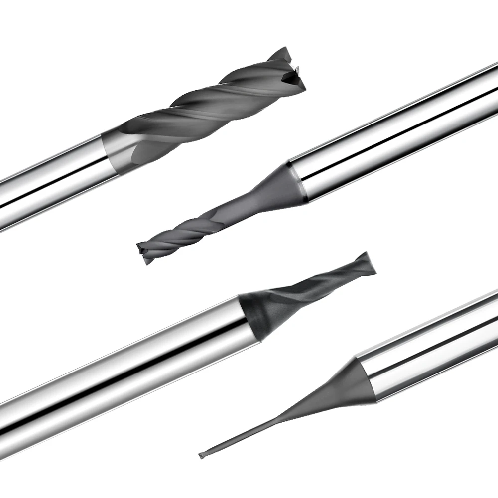
You can professionally assess a tool by examining the physical details. For HRC65 milling cutter bits, the end-face relief angle is the ultimate “touchstone.” Under 50x magnification, look for irregular rounding or burrs at the edge intersections. If you see them, that tool will leave “step marks” or overcut the transition between the wall and bottom. A genuine precision tool has exquisitely sharp, symmetrical geometric planes to keep cutting forces balanced.
Use a tool presetter to check consistency. If run-out variation between four edges exceeds 0.003mm, only one or two edges will do all the work. This shortens life and causes alternating light/dark streaks on your mirror finish. Also, check the flute polish; visible grinding marks are breeding grounds for built-up edge (BUE) when evacuating hard chips.
Cost vs Efficiency: Evaluating the Machining Area per Tool
Shift your focus from “unit price” to “machining area per unit.” When budgeting for a batch of molds, track the total surface area an end mill cutter bit can maintain a mirror finish over. Cheap tools might last 10 minutes before the coating peels. High-quality tools may cost 20% more but allow for 5 hours of continuous machining without downtime for compensation.
If you want the lowest cost per part, establish a model that factors in tool cost, machine hourly rates, and manual polishing time. Typically, a 10% increase in tool price that yields a 20% efficiency gain and 30% less polishing is a massive financial win. This is the rational approach for any mature facility.
Every drawing and material is unique. If you are struggling with surface quality or need a specific strategy for high-nickel alloys or cold-work steels, we are ready to discuss your specific conditions. Let’s explore how to optimize your process system together.