


To optimize the performance of end mills, understanding the critical relationship between the speed at which the tool rotates (RPM) and the rate at which the tool advances through the material (feed rate) is essential. These parameters directly influence the finish quality, machining efficiency, and tool lifespan. Speed, measured in revolutions per minute (RPM), determines the velocity at which the cutting edge engages the material. In contrast, feed rate, expressed in inches per minute (IPM), dictates how fast the tool moves through the material.
In achieving peak performance, selecting a speed and feed that complement the machined material, the tool’s geometry, and the tool’s finish is imperative. Misapplication of these parameters can lead to suboptimal outcomes, such as poor surface finish, excessive wear on the tool, or even catastrophic tool failure. Therefore, leveraging the correct formulas and manufacturer recommendations to calculate optimal settings is fundamental to maximizing efficiency and achieving superior machining results.
What Are End Mill Speed and Feed?

Understanding the Basics of Speed and Feed
At the core of precision milling operations is the ability to finely tune the spindle speed (RPM) and feed rate (IPM) for end mills. Spindle speed refers to the rate at which the cutting tool rotates, impacting how effectively the tool cuts through the material. A higher speed typically results in a smoother finish but can elevate the risk of overheating and tool wear if not accurately matched to the material’s materials.
On the other hand, the feed rate determines the speed at which the end mill moves through the material along its cutting path. An optimally set feed rate can significantly enhance the quality of the cut and the efficiency of material removal. However, a feed rate that is too rapid might overwhelm the tool’s control capacity, leading to suboptimal finishes or tool damage.
The Role of Spindle Speed and Feed Rate in Milling
- Surface Finish and Precision: Appropriate spindle speeds can produce cleaner cuts, improving the surface finish. Concurrently, a harmonized feed rate ensures uniform material removal, which is vital for precision milling.
- Tool Wear: Selecting a suitable combination of speed and feed minimizes the wear and tear on the tool, extending its service life while ensuring consistent performance.
- Material Removal Rate (MRR): Optimizing speed and feed is crucial for maximizing MRR, the volume of material removed over time. Efficient MRR is a balance – too slow can be time-consuming and costly, while too fast may reduce precision and tool life.
- Thermal Management: Proper speed and feed settings help manage the heat generated during milling. Excessive heat can alter the material properties and diminish tool life.
Critical Differences Between Surface Speed and Feed Rate
- Surface speed is a measure of the speed at which the tool’s exterior moves across the material’s surface. It’s often Specialized in terms of speed at the tool’s edge, which is crucial for determining the ideal RPM for different materials.
- Feed rate, in contrast, is concerned with the movement of the tool into or through the material. It’s a direIt’seasure of how fast the material is being cut or machined.
Understanding and applying these parameters with precision is foundational to achieving desired machining outcomes, enhancing productivity, and ensuring the longevity of tools in milling operations.
How to Calculate Speed and Feed for Your Milling Operations
Calculating the optimal speed and feed for your milling operations can significantly influence the quality and efficiency of the machining process. Utilizing a Speed and Feed Calculator simplifies this process by providing precise formulas tailored to various conditions, offering a standardized approach for determining the best settings.
Using a Speed and Feed Calculator for Precision
A Speed and Feed Calculator considers multiple variables to recommend optimal machining parameters. These include:
- Tool Diameter: The size of the end mill or tool affects the surface speed and, consequently, the ideal RPM.
- Material Type: Different materials have unique properties that influence cutting speed. For example, aluminum requires a different approach than steel.
- Cutting Speed (SFM): This is determined based on the material and tool type. Each material has an optimal cutting speed for efficient machining without causing excessive wear on the tool.
- Spindle Speed (RPM): This is calculated based on the cutting speed and tool diameter.
- Feed Per Tooth (FPT): The advancement per tooth affects the finish and the rate at which material is removed.
- The number of Teeth on the Tool determines the feed rate, balancing the load on each tooth to avoid damage and ensure efficient cutting.
Formulas for Calculating End Mill Speeds and Feeds
The basic formulas used are as follows:
- Spindle Speed (RPM) = (Cutting Speed * 4) / Tool Diameter
- Feed Rate (IPM) = RPM * Number of Teeth * Feed Per Tooth
Adjusting Calculations for Material and Tool Type
Adjustments are necessary to cater to the material being machined and the cutting tool used. For instance, more rigid materials require slower speeds to reduce wear on the tool, while softer materials can be machined at higher speeds. Similarly, the tool material (e.g., carbide, high-speed steel) affects the achievable speeds and feeds.
In conclusion, a Speed and Feed Calculator provides a foundational starting point for determining milling parameters. However, experience and adjustments based on specific machining conditions are indispensable for achieving the desired outcome. Proper application of these principles ensures efficient material removal, optimal tool life, and high-quality surface finishes, enhancing overall productivity in milling operations.
Choosing the Right End Mill for Optimal Speed and Feed
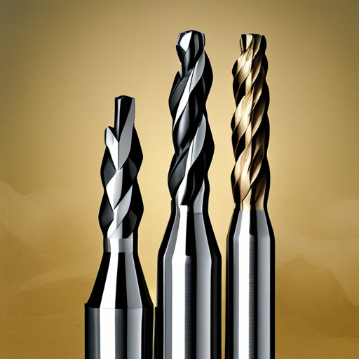
2 Flute vs. 4 Flute vs. 6 Flute End Mills
When selecting the appropriate end mill for a specific task, the number of flutes on the tool plays a critical role in the performance and the finish of the piece.
- 2 Flute End Mills are typically used for machining materials, such as aluminum, where chip evacuation is paramount. With fewer flutes, there are more chips to escape, reducing the risk of re-cutting and heat buildup.
- 4 Flute End Mills represent a balance between chip evacuation and the ability to carry out finer finishes. They’re suiTsuiThey’reroader range of materials, including steel and cast iron. The additional flutes allow for higher feed rates due to the increased cutting surface.
- 6 Flute End Mills are designed for finishing operations requiring a high-quality surface finish. They have less chip evacuation space but provide a smooth finish on materials like stainless steel or titanium.
Carbide End Mills Versus HSS: What You Need to Know
When comparing tool materials, Carbide and High-Speed Steel (HSS) are the most prevalent in end-mill construction.
- Carbide End Mills are more complex and brittle, offering superior speed capabilities and longer tool life due to their heat resistance. They’re suiTsuiThey’re for-speed operations on more complex materials but can be more expensive.
- High-speed steel (HSS) End Mills are tougher and can absorb more vibration and shock during cutting. They are more versatile in application and typically cost less than carbide tools, but they may not provide the same level of precision or tool life under high-speed conditions.
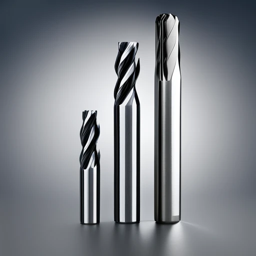
Impact of Tool Diameter on Speed and Feed Rates
The diameter of the tool significantly impacts the achievable speed and feed rates in milling operations.
- Smaller Diameter Tools: Smaller tools can operate at higher RPMs but may require lower feed rates due to the lower structural strength and the risk of tool deflection.
- More Extensive Diameter Tools: These tools can withstand higher feed rates due to their increased strength and stability. However, the achievable RPM decreases as the tool diameter increases due to the higher circumference that each flute travels per rotation.
In conclusion, the choice between 2, 4, and 6 flute end mills largely depends on the machined material and the operation type (e.g., roughing vs. finishing). Similarly, the decision between carbide and HSS tools involves weighing the cost against the operation’s performance needs. Finally, tool diameter directly influences the optimal speed and feed rates, balancing the efficiency of material removal and tool longevity.
Common Problems and Solutions in Speed and Feed Calculations
Overcoming Challenges with Chatter and Deflection
Chatter and deflection in milling operations can critically undermine the quality of the workpiece and shorten tool life. The primary strategy to combat these issues involves optimizing speeds and feeds, ensuring proper tool path selection, and employing the right tool geometry for the material and operation.
- Optimizing Speeds and Feeds: Adjusting the cutting speed (RPM) and feed rate to suit the material, tool diameter, and type of operation can significantly reduce chatter. Use manufacturer-recommended parameters as a starting point and make incremental adjustments based on observed performance.
- Tool Path Selection: Modern CAM software offers advanced tool paths, such as trochoidal milling or peel milling, designed to reduce lateral forces on the tool, which in turn helps minimize deflection and chatter.
- Tool Geometry: Select a tool with the appropriate length-to-diameter ratio, flute count, and helix angle for your material and application. Shorter tools with higher flute counts and variable helix angles can often resist deflection and reduce chatter more effectively.
Adjusting Speed and Feed to Avoid Tool Breakage
Tool breakage is often a result of excessive feed rates, improper tool selection, or inadequate coolant flow. To prevent breakage:
- Feed Rate Adjustment: Reduce the feed rate to decrease the force on the tool without significantly sacrificing productivity. Utilize chip thinning calculations to adjust feed rates, particularly for high-efficiency milling strategies.
- Tool Selection: Use tools with appropriate coatings and substrate materials designed for the machined material. Tools with reinforced core diameters may also offer increased strength.
- Coolant Management: Ensure adequate coolant flow to reduce heat accumulation at the tool-workpiece interface. High-pressure coolant systems can improve chip evacuation and reduce thermal stress on the tool.
Maximizing Efficiency with Proper Chip Load Management
Managing chip load is crucial for maximizing the efficiency of milling operations and extending tool life. Proper chip load ensures effective heat dissipation and reduces tool wear.
- Calculating Chip Load: The chip load can be calculated by dividing the feed rate by the product of the number of cutting edges and the spindle speed. Adjust the feed rate to achieve the optimal chip load for the tool and material.
- Material-Specific Adjustments: Adapt chip load parameters based on the material being machined. More complex materials typically require a lower chip load, while softer materials can tolerate higher chip loads.
- Use of Chip Breakers and Variable Helix Tools: Tools with chip breakers or variable helix angles can manipulate chip formation, promoting better chip evacuation and heat management.
By diligently addressing these challenges through informed adjustments and selections, manufacturers can balance productivity, tool life, and part quality in their milling operations.
Advanced Tips for Mastering Speed and Feed in High-Performance Milling

Utilizing High-Performance End Mills for Superior Results
High-performance end mills are engineered to exceed the capabilities of standard end mills, offering enhanced geometries and materials tailored for specific applications. By implementing these specialized tools, manufacturers can achieve superior results in both efficiency and quality.
- Tool Material and Coating: Select end mills made from substrates such as carbide, cobalt, or high-speed steel (HSS), enhanced with coatings like TiAlN or AlCrN, to improve heat resistance and reduce wear in demanding applications.
- Geometric Innovations: Opt for tools featuring advanced geometries, such as variable helix angles and unequal flute spacing. These design innovations minimize vibration, allowing for higher machining accuracy and better surface finishes.
- Tool Selection: Match the end mill to the application. For instance, use ball nose end mills for 3D contouring or chamfer mills for creating angles, ensuring the tool’s design has the desired outcome.
Strategies for Milling Difficult-to-Machine Materials
Milling materials such as titanium, stainless steel, and superalloys pose distinct challenges due to their high strength and thermal resistance. Effective strategies include:
- Reduced Cutting Speeds: Adjust spindle speeds downward to mitigate the thermal buildup and minimize tool wear.
- Increased Feed Rate: Apply higher feed rates within the tool’s capatools to prevent work hardening of the material.
- Tool Path Optimization: Implement climb milling and utilize CAM software to generate tool paths that distribute the load evenly, reducing the chance of tool failure.
Adjusting Speed and Feed for Complex Milling Operations
Complex milling operations that involve intricate shapes or deep cavities require careful adjustments to speed and feed:
- Speed Reduction in Corners: Slow down spindle speed when machining corners to limit tool deflection and prevent chatter.
- Feed Rate Modulation: Adjust feed rates dynamically across different sections of the part to maintain a consistent chip load, especially when transitioning between varied geometries.
- Use of Trochoidal Milling: Implement trochoidal or peel milling strategies for efficient material removal under challenging regions, minimizing tool engagement and thermal stress.
By adhering to these detailed strategies and adjustments for each scenario, manufacturers can significantly enhance the performance of their milling operations, achieving a balance between productivity, tool life, and quality of the finished part.
Expert Perspectives: Tips from Veteran Machinists
Practical Advice from the Shop Floor: Leveraging Experience to Optimize Speed and Feed
Veteran machinists often emphasize the importance of leveraging experience and technology to fine-tune machining operations for optimal efficiency and precision. Key insights include:
- Start with Manufacturer Recommendations: Use tooling manufacturer manufacturers ‘ feedback as a starting point, but don’t hesitate to assess to material variances and specific job requirements.
- Document Adjustments: Keep detailed records of any changes made to speed and feed rates for specific materials and tooling combinations. This documentation creates a valuable knowledge base for future operations.
- Listen to the Machine: Experienced machinists can often “hear” when”the “machine is operating optimally. A smooth, steady sound indicates good cutting action, whereas a high-pitched squeal may suggest too fast a feed rate or too slow a spindle speed.
- Monitor Tool Wear: Regular inspection of cutting tools for signs of wear or damage can provide insights into whether speed and feed rates need adjustment.
- Incremental Adjustments: Make speed and feed adjustments in small, incremental steps, especially when approaching the limits of the tool’s capabilities, to avoid damage and ensure dimensional accuracy.
Virtual Milling and Simulation for Speed and Feed Optimization
Advancements in computer-aided manufacturing (CAM) software have introduced powerful virtual milling and simulation tools that can significantly enhance speed and feed optimization:
- Virtual Testing of Tool Paths: Use CAM simulations to test and validate tool paths before actual machining. This helps identify and eliminate potential issues like collisions, excessive tool load, or inefficient tool paths.
- Material Removal Rate (MRR) Analysis: Simulation software can estimate MRR, helping optimize speed and feed rates to balance high productivity and tool wear.
- Thermal and Force Analysis: Some advanced simulation tools can analyze the thermal impact and cutting forces on the tool and workpiece, allowing for more informed adjustments to speed and feed rates.
- Feedback Loop Integration: Incorporate simulation feedback into the machining process, using actual machining data to refine and update simulation parameters for continuous improvement.
By combining the practical, hands-on advice from seasoned machinists with the analytical power of virtual milling simulations, manufacturers can achieve a synergistic approach to optimizing speed and feed settings, improving efficiency, tool life, and product quality.
References
1. Source: Journal of Manufacturing Science and Engineering – “Optimizati”n of End Milling Parameters for Improving Surface Finish Using Taguchi Method”
- URL: http”://asmedigitalcollection.asme.org/manufacturingscience/article/doi/10.1115/1.4034869/478321
- Annotation: This article from the Journal of Manufacturing Science and Engineering presents a scientific study on optimizing end milling parameters, including speed and feed rates, to enhance the surface finish of machined parts. Utilizing the Taguchi method for experiment design, the research evaluates how different combinations of machining parameters affect surface quality outcomes. This peer-reviewed source provides a detailed methodology and analysis, making it valuable for professionals seeking to understand the empirical relationship between end mill speed, feed, and machining performance.
2. Source: Modern Machine Shop – “Understand” End Mill Speeds and Feeds”
- URL: http”://www.mmsonline.com/articles/understanding-end-mill-speeds-and-feeds
- Annotation: This article from Modern Machine Shop offers a comprehensive overview of the principles behind selecting appropriate speeds and feeds for end-milling operations. It breaks down the factors that influence these parameters, such as material properties, tool geometry, and cutting environment, providing a foundation for making informed decisions in machining practices. The source is presented professionally, aiming to demystify complex concepts for a broader audience, including machining practitioners and engineers looking for guidance on optimizing their milling processes.
3. Source: Harvey Performance CompanyCalculationatin” Speeds and Feeds for Your Tooling Inventory”
- URL: http”://www.harveyperformance.com/in-the-loupe/calculating-speeds-and-feeds/
- Annotation: The Harvey Performance Company provides an in-depth guide on calculating optimal speeds and feeds for various tooling inventory, including end mills. The guide emphasizes the importance of understanding the interaction between the cutting tool and workpiece material, offering practical formulas and examples to determine the best machining parameters. This manufacturer is particularly relevant for professionals aiming to optimize their tooling performance through precise calculations and adjustments in speed and feed settings.
Frequently Asked Questions

Q: What are the fundamental principles of determining end mills’ rpm, feeds, and speeds?
A: The fundamental principles involve calculating the optimal revolutions per minute (rpm), feeds, and speeds for a given end mill operation. This process depends on several factors, including the cutter’s matter such as HSS or carbide cutters), the workpiece material, the diameter of the mill, the depth of cut, and the width of the cut. The ultimate goal is to maximize efficiency and tool life while ensuring a high-quality finish on the workpiece.
Q: How do I calculate the correct rpm for my endmill?
A: To calculate the correct revolutions per minute (rpm) for your endmill, use the formula RPM = (sfm x 3.82) / diameter of the mill, where sfm stands for surface feet per minute, a standard metric for cutting speed. The same value depends on your cutting tool and workpiece material. Remember to adjust the speed based on factors such as tool deflection, the complexity of the slot, and whether you’re using mill or carbide cutters.
Q: What do “feeds and “peeds” mean in the inco-text”text of CNC machining?
A: In CNC machining, “feeds and refers” refers to”two distinct yet related parameters: feed rate and cutting speed. The feed rate (measured in inches per minute or rpm) dictates how fast the cutter moves through the workpiece, while cutting speed (measured in surface feet per minute or sfm) refers to the speed of the cutter navigating through the material. Properly setting these parameters is vital for optimizing the machining process, ensuring efficient material removal, and prolonging the life of the cutting tool.
Q: What role does the number of flutes on an end mill play in determining feeds and speeds?
A: The number of flutes on an end mill significantly impacts feeds and speeds, as it affects the amount of material each tooth has to remove per revolution (chip load per tooth) and the tool’s ability to evacuate chips. End mills with fewer flutes allow for higher feed rates because of the larger chip load capacity but may have lower cutting speeds. Conversely, end mills with more flutes can operate at higher speeds but might require lower feed rates to prevent chip packing and tool deflection.
Q: How can I improve the performance of my CNC machine’s machine speed settings for high-performance end mills?
A: Experiment with tweaking the cutting feed and feed per tooth based on the cutter’s declutter, the material being machined, and the type of operation (rough or finish). Additionally, using end mills with the appropriate number of flutes for the task and ensuring the cutter is suited for the material can significantly enhance performance. Implementing proper coolant or lubrication can also optimize cutting conditions.
Q: What is the difference between surface and feed speeds in CNC machining?
A: Surface speed, measured in surface feet per minute (SFM) or meters per minute, refers to the speed at which the tool’s cutting edge moves against the workpiece. In contrast, feed speed, measured in inches per minute (rpm) or millimeters per minute, indicates the rate at which the workpiece is fed into the tool or the tool is moved across the workpiece. Surface speed mainly influences the cutter’s cutter sife, while feed speed affects the material removal rate and the cut surface’s quality.
Q: Can adjusting the speed or feed compensate for using an end mill with fewer flutes?
A: Adjusting the speed or feed can compensate to some extent for using an end mill with fewer flutes. Increasing the rpm and carefully managing the feed rate can help achieve efficient material removal rates even with fewer flutes. However, it’s crucial to monitor tool deflection and wear it closely, as these adjustments might place additional stress on the endmill. Optimal adjustment balances productivity, tool life, and workpiece quality.
Q: What safety precautions should be taken when adjusting end mill feeds and speeds?
A: Safety precautions when adjusting end mill feeds and speeds include wearing appropriate personal protective equipment (PPE), ensuring the machine is correctly set up and that there are no loose parts or fixtures, and verifying that workpieces are securely clamped. Additionally, gradually adjusting speeds and feeds rather than making significant changes simultaneously can help prevent tool breakage and potential injury. Always follow the CNC machine and tool manufacturers for recommended speeds, feeds, and safety instructions.
Recommended Reading: Unlocking the Versatility of End Mills: Essential Insights


