When helping clients optimize graphite electrode machining, we frequently see a familiar challenge. A shop installs high-speed CNC machining centers and buys premium graphite end mills. Yet, once mass production begins, issues quickly emerge—inconsistent tool life, dimensional drift, poor surface finish, and equipment failure caused by abrasive graphite dust.
We vividly recall a project with a European mold manufacturer. They were machining complex graphite electrodes with deep cavities, narrow slots, and tight-tolerance contours. Initial prototype tests passed without issues. However, full-scale production triggered rapid tool wear and incomplete machining in deep cavities. On-site diagnostic data revealed the root cause: the issue was not just the tool itself. The problem lay in machine setup, parameter matching, and overall system integration.
This issue occurs frequently in field operations. Many manufacturers simply switch to a more wear-resistant cutting tool. They overlook that CNC graphite machining requires a holistic engineering system. Spindle dynamic performance, structural rigidity, tool holder runout, dust collection capacity, workholding stability, and cutting parameters all directly impact final part quality.
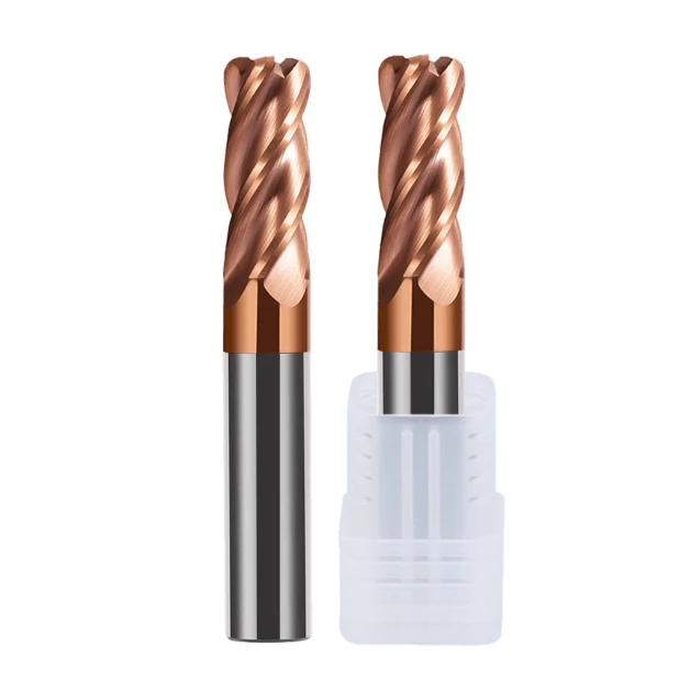
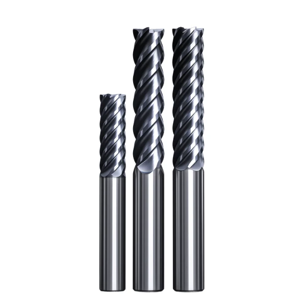
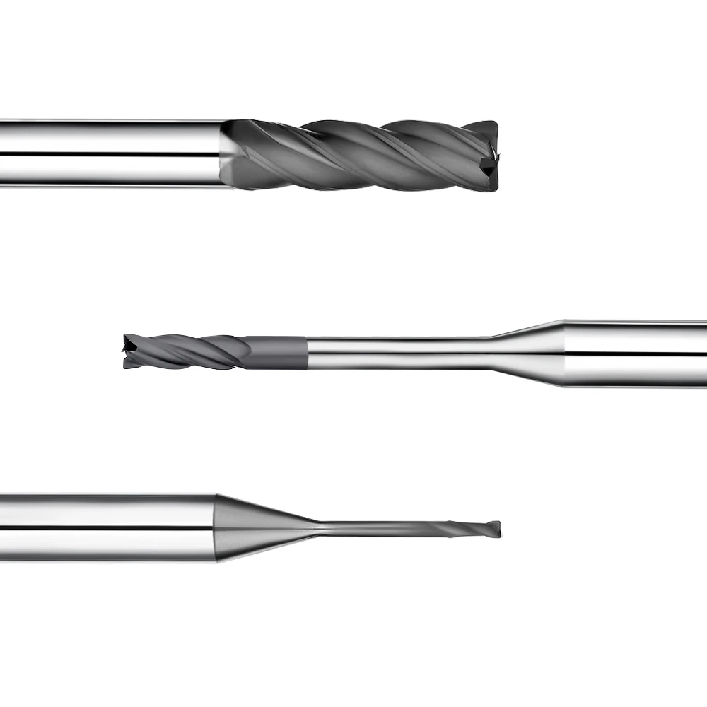
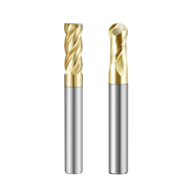
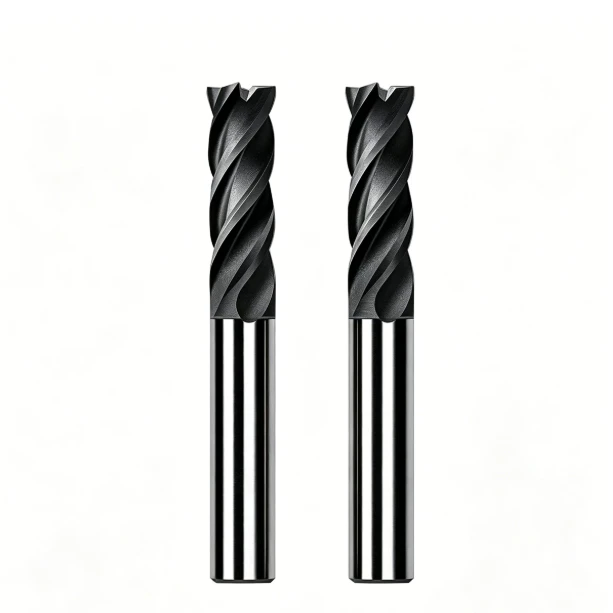
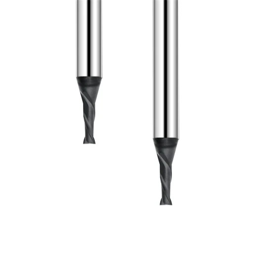
A stable graphite machining system requires systematic optimization based on material behavior, part geometry, and cycle time goals. For deep-cavity electrodes, selecting long-neck graphite end mills reduces tool interference and stabilizes cutting. During high-speed finishing, using diamond-coated graphite milling cutters drastically cuts abrasive wear from fine particles and extends tool life.
Many machine shops incorrectly apply speed and feed parameters meant for mold steels or aluminum alloys. Graphite requires entirely different cutting dynamics. Adjusting spindle speed, feed rate, depth of cut, and chip evacuation strategies is essential. Only by aligning machine configuration, parameters, and cutter selection can shops achieve stable, high-efficiency graphite machining.
Based on years of hands-on field experience, this article outlines how to build a reliable, high-performance graphite machining system. We cover key machine configurations, parameter optimizations, tool selection strategies, and systemic solutions to help you reduce trial-and-error costs while maximizing precision and throughput.
If your high-speed CNC equipment still struggles with tool life or dimensional consistency, consider this: Is it just the cutting tool that needs adjustment, or is your entire CNC system setup overdue for optimization?
Graphite Milling Machine Setup: Key Engineering Factors in CNC Graphite Machining Configuration
In our graphite electrode machining projects, clients usually focus on tool geometry and feed rates first. However, field experience shows that consistent precision relies heavily on the initial equipment configuration. Setting up a graphite milling machine requires more than just dialing in speeds; it demands a thorough review of machine rigidity, dynamic spindle performance, workholding setups, and dust management.
We once worked with a mold shop facing severe dimensional drift after running large graphite electrodes continuously for several hours. On-site diagnostics showed the tools were fine; the real culprits were machine vibration, poor dust evacuation, and mismatched machine capabilities. Verifying your machine’s foundational setup before swapping tools is often the fastest path to fixing production bottlenecks.
CNC Mill Setup for Graphite: Spindle, Rigidity, and Machine Precision Requirements
When configuring a CNC mill for graphite, we prioritize overall mechanical stability over raw spindle speed. Although graphite exerts low cutting resistance, abrasive dust quickly penetrates guideways and degrades motion accuracy. Poor machine rigidity creates micro-vibrations during high-speed cuts, causing premature tool wear, poor surface finishes, and dimensional errors.
We advise clients to verify high-speed spindle balance, minimize tool holder runout, and use rigid workholding setups. Critical factors include positioning accuracy, thermal growth control, and repeatability during extended runs. When using micro-diameter graphite end mills for narrow slots, even tiny dynamic runouts can instantly snap fragile cutting edges.
Graphite Machining System: Integrated Configuration Logic
A reliable graphite machining system requires seamless alignment between machine tools, cutting tools, parameters, and peripheral equipment. Standard high-speed machining centers may handle basic electrodes, but high-purity graphite and complex 3D contours demand upgraded spindle dynamics, enclosed dust collection systems, and dedicated diamond-coated cutters.
When optimizing client workflows, we focus on three core areas: ensuring stable high-speed CNC motion, selecting ideal tool geometries like long-neck graphite end mills for deep cavities, and balancing chip loads. This holistic approach builds a predictable precision graphite machining process that does not rely on constant manual adjustments.
CNC Graphite Machining: Machine Tool Parameter Settings Affecting Stability
In production environments, machining failures often stem from applying traditional metal-cutting mindsets to graphite. Operators frequently run depth-of-cut and feed settings meant for mold steel, causing excessive cutting forces, severe edge chipping on workpieces, and hazardous dust buildup that overwhelms the vacuum extraction system.
We systematically recalibrate spindle speeds, feed rates, axial depth of cut, and radial engagement for specific graphite grades and cavity geometries. High-speed finishing requires light radial loads to protect fine ribs, while roughing prioritizes smooth chip evacuation. Fine-tuning these graphite machining speeds and feeds eliminates guesswork and guarantees long-term process repeatability.
If you already use specialized tooling but still face dimensional instability or short tool life, re-evaluate your overall CNC graphite machining configuration—the solution likely lies in your system setup, not just the cutter.

CNC Graphite Machining Process: Machine Tool and Process Preparation Before Graphite Processing
In our field operations, pre-process preparation determines whether mass production remains stable. Many shops focus solely on initial tool performance and feed speeds during sample runs. However, when transitioning to volume manufacturing, minor issues like datum shift, fine dust buildup, and spindle runout compound quickly. Establishing a standardized CNC graphite machining process before cutting metal is far more effective than troubleshooting dimensional errors later.
We once supported a mold shop running continuous batch production of intricate graphite electrodes. Initial samples met specs, but dimensional drift quickly ruined production parts over long shifts. On-site inspection revealed the core issue: inconsistent workholding repeatability, insufficient clamping rigidity, and poor dust cleanup routines. Establishing standardized pre-machining protocols resolved their process instability immediately.
Graphite Milling Machine Setup: Tool Clamping, Workpiece Positioning, and Machining Environment Optimization
A robust graphite milling machine setup must guarantee rigid interface connections between tool, holder, and spindle. Although graphite generates lower cutting resistance than steel, high spindle speeds amplify tool runout exponentially. When using micro-diameter cutters for precision electrodes, even a few microns of runout causes edge chipping, poor surface finish, and premature tool failure.
We advise operators to inspect collet accuracy, chuck cleanliness, and spindle taper mating surfaces before every production run. Workholding must prevent part distortion on large blocks while ensuring rigid datum positioning for small, complex electrodes. For deep cavities, evaluating tool overhang and vibration limits when applying a long neck graphite end mill avoids chatter marks and costly scrap.
Graphite Dust Control: Graphite Dust Management and Equipment Protection Design
Long-term project data shows that many machining anomalies stem directly from inadequate dust management. High-speed milling breaks graphite into abrasive micro-particles. If not evacuated immediately, this airborne dust clouds operator vision and settles inside machine guideways, linear scales, and protective way covers, deteriorating machine accuracy over time.
For example, a customer processed graphite on standard vertical machining centers without specialized dust extraction. While initial accuracy was fine, fine graphite dust infiltrated motion components, degrading linear positioning accuracy within months. Implementing an integrated graphite dust control system—combining heavy-duty vacuum extraction with sealed enclosures—protects critical machinery and ensures consistent long-term tolerance hold.
Graphite Machining Solution: System Optimization from Equipment Configuration to Processing Process
Resolving production bottlenecks in graphite milling requires an integrated approach rather than a quick single-factor fix. A comprehensive graphite machining solution connects machine dynamics, custom tool geometries, optimized parameters, and shop-floor protocols. Because every shop operates different machine models and graphite material grades, optimal setups must be customized to your specific production rhythm.
We evaluate spindle rpm limits, tool wear patterns, cycle times, and inspection reports before adjusting parameter suites. Upgrading to advanced tool coatings helps, but without structural machine rigidity and proper vacuum collection, tool upgrades yield minimal ROI. Ask yourself: Has your engineering team optimized the entire graphite machining ecosystem, or just the cutting tool?
Graphite Machining Speed and Feed: Methods for Optimizing CNC Graphite Milling Parameters
Cutting parameters serve as the backbone of process stability in graphite electrode production. Shops machining graphite for the first time often apply parameters meant for aluminum or mold steels. However, graphite exhibits vastly different fracture mechanics, abrasive dust formation, and edge-loading behavior. Optimizing your graphite machining speed and feed settings requires a holistic assessment of machine rigidity, material density, tool geometry, and target surface finish.
We once helped a client who tried boosting output by simultaneously maxing out spindle speed and feed rates on high-purity graphite. Instead of shortening cycle times, the aggressive parameters caused rapid tool flank wear and severe edge chipping. We stabilized the process by balancing spindle RPM, feed per tooth, and depth of cut. Pushing parameters to arbitrary extremes fails; finding the sweet spot for your specific machine setup yields consistent results.
Graphite Cutting Speed: Selecting Spindle Speed for High-Speed Graphite Machining
Spindle speed directly dictates cutting temperature, chip formation, and edge longevity during graphite milling operations. An optimized graphite cutting speed maintains steady shearing action while eliminating premature tool wear. High-speed machining yields excellent throughput on precision electrodes, provided your spindle, tool holding, and dust extraction systems remain rock-solid.
We never recommend generic RPM numbers across different machining centers. Fine features and micro-electrodes require vibration-free cutting to protect surface integrity, whereas roughing massive blocks demands high material removal rates (MRR). When running diamond-coated end mills at elevated speeds, matching parameter aggressiveness to coating capabilities prevents coating delamination and premature cutter failure.
Graphite Milling Feed Rate – Balancing Feed Rate and Cutting Efficiency
Operators often overlook feed rates compared to spindle speed, yet feed rate determines chip load, edge wear, and workpiece chipping. If the graphite milling feed rate is too low, the tool rubs excessively, generating frictional heat and polishing the material. Conversely, an excessively high feed rate creates heavy impact forces that chip fragile electrode ribs.
During one mold project, a client cranked up feed rates to cut cycle time, causing micro-chipping on thin-walled electrode features. We resolved the issue by implementing adaptive feed rate reduction in tight corners and optimizing toolpaths. For complex geometries, programming distinct feed rates for roughing, semi-finishing, and finishing stages delivers far superior stability than relying on fixed feed rates.
Graphite Milling Parameters – Adjustment Strategies for Different Graphite Materials
Graphite grades vary wildly, ranging from coarse mold-grade materials to ultra-fine high-purity graphite used in semiconductor fabrication. Because grain size and shore hardness differ across grades, optimal graphite milling parameters must adapt accordingly. What works seamlessly on standard electrode material may destroy fine features on dense, high-purity graphite.
For fine-grained graphite requiring mirror-like surface finishes, we favor light radial loads and controlled feed rates. For heavy roughing, we optimize axial depth of cut to maximize material removal rates without overloading the cutter. We advise engineering teams to track spindle load and edge wear patterns during initial parameter setup to build repeatable production standards.
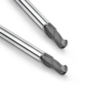
Graphite End Mill Selection: Tool Choice and Its Impact on CNC Graphite Machining Performance
Selecting the proper graphite end mill is often the defining factor in achieving long-term machining stability. When faced with short tool life or poor surface finishes, operators frequently jump to adjusting feeds and speeds. However, field experience proves that matching cutter geometry to part topology yields far better results than simply cranking up parameters.
We once assisted a mold maker struggling with severe tool chatter, poor chip evacuation, and dimensional error in deep cavity slots. Standard cutters worked fine in shallow regions but failed as cavity depth increased. By systematically evaluating tool overhang, neck relief, flute count, and diamond coatings, we stabilized their process and eliminated scrap.
Long Neck Graphite End Mill: Tool Application in Deep-Cavity Graphite Electrode Machining
Machining deep electrode cavities presents a constant battle between reach and rigidity. Standard tools often fail due to shank interference, while overly extended tools introduce severe chatter and tool deflection. Selecting a high-performance long neck graphite end mill allows shops to safely reach deep slots and tight internal radii without sacrificing cutting stability.
Longer reach is not always better; unnecessary tool overhang drastically degrades dynamic rigidity. We carefully match neck length, core thickness, and relief angles to the exact depth of cut. For deep-cavity roughing, we prioritize core strength to handle heavy chip loads, whereas finishing operations demand minimal dynamic runout to guarantee tight tolerances.
Diamond Coating for Graphite Milling: Extending Tool Life
Graphite is soft, but its micro-granular structure acts like fine sandpaper, subjecting cutting edges to extreme abrasive wear. Standard carbide end mills dull rapidly under high-speed milling, leading to burr formation and dimensional drift. Applying specialized CVD diamond coating for graphite milling creates a hard protective barrier that drastically slows flank wear and extends tool life.
In high-purity graphite trials, diamond coated tools maintained razor-sharp edges up to ten times longer than uncoated carbide. However, coating performance depends heavily on substrate bonding and cutting parameters. While uncoated carbide suffices for quick prototype runs, high-volume production demands premium diamond coated cutters to maintain dimensional repeatability.
Graphite Milling Cutter Supplier: Selection Criteria for Professional Suppliers
Partnering with the right graphite milling cutter supplier goes far beyond ordering catalog part numbers. High-precision graphite machining requires suppliers who provide hands-on technical application support. We evaluate vendors based on their tool design expertise, substrate quality, test data transparency, and willingness to troubleshoot on the shop floor.
Many shops cycle through multiple tool brands without success because vendors offer off-the-shelf tools without understanding machine dynamics. A true partner analyzes your spindle capabilities, graphite grades, and toolpaths to recommend custom tool geometries. Choosing a supplier invested in collaborative process optimization yields significantly higher ROI than simply buying cheap end mills.
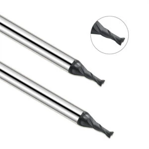
Optimizing the Graphite Machining System: Engineering Solutions to Enhance Machining Precision and Production Efficiency
Maintaining long-term precision and output consistency across volume production remains a major hurdle in electrode manufacturing. Achieving flawless results on a single prototype does not guarantee stable mass production. As cutting hours accumulate, tool wear, thermal spindle growth, and ambient temperature shifts cause subtle process variations that ruin batch tolerances.
We supported a mold maker experiencing batch-to-batch dimensional drift during high-volume electrode production. While initial test parts met specs, multi-shift runs showed unacceptable tolerance scatter. Root-cause analysis traced the issue to unmanaged tool wear, inconsistent finishing allowances, and sporadic machine maintenance. Implementing a holistic graphite machining system created seamless synergy between machine dynamics, tooling, and shop-floor protocols.
CNC Graphite Machining Accuracy: Controlling Dimensional Precision and Surface Quality
Sustaining high-precision electrode tolerances requires managing every variable in the machining chain. Workpiece positioning repeatability, dynamic spindle runout, real-time wear compensation, and finishing allowance control directly dictate accuracy. Isolating cutting tool performance while ignoring workholding or thermal drift will never deliver consistent CNC graphite machining accuracy.
During one high-precision project, a client faced dimensional errors during multi-cavity electrode runs and blamed short tool life. On-site diagnostics showed the real causes: static offset parameters that ignored tool wear progression and uneven stock allowance during pre-finishing passes. We resolved the drift by introducing dynamic tool wear compensation and optimizing finishing toolpaths based on CMM inspection data.
Graphite Machining Solution: Reducing Tool Wear and Enhancing Machining Stability
Tool wear in graphite milling stems from abrasive micro-mechanics rather than thermal overload. Effective wear reduction relies on balancing cutter geometry, coating selection, parameter aggressiveness, and dust extraction efficiency. A truly effective graphite machining solution addresses root causes across the entire cutting environment rather than simply buying expensive cutters.
When analyzing tool degradation in continuous electrode production, we inspect wear patterns under magnification before altering parameters. Sometimes adjusting radial engagement or switching to custom flute geometries improves stability instantly. However, running aggressive speeds without proper vacuum extraction will prematurely destroy even premium cutters. Always analyze wear mechanics before altering your tooling suite.
High-Performance Graphite Machining System: Boosting Reliability in Batch Production
In high-volume graphite manufacturing, long-term repeatability outweighs single-part cycle speeds. True process maturity means holding identical tolerances across different operator shifts and material lots. Building a high-performance graphite machining system requires standardized tool-change protocols, real-time spindle load logging, and strict preventive maintenance schedules.
We helped an electrode shop eliminate shift-to-shift quality variation caused by operators manually tweaking parameters. By establishing standardized operating procedures—including fixed tool life management, locked parameter sets, and mandatory vacuum maintenance—we stabilized their daily yield. Upgrading your shop’s capabilities does not require over-complicated equipment; it requires matching proven machines, tools, and processes to your exact product requirements.
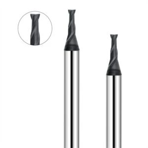
Building a Reliable Graphite Machining System by Optimizing CNC Machine Setup
Years of field engineering in electrode manufacturing reinforce a fundamental truth: process stability never comes from optimizing a single variable in isolation. Whether upgrading machine configurations, choosing tool geometry, or tweaking feed parameters, every decision must align with shop-floor conditions. Shops often hope replacing a worn tool will fix production errors, but diagnostic root causes usually point to poor alignment between spindle performance, workholding stability, dust extraction, and tool selection.
Establishing a repeatable production line requires a complete understanding of your overarching graphite machining system. Every phase—from pre-machining equipment prep and precise graphite milling machine setup to tool selection and batch parameters—directly governs finished quality. If your shop faces quality bottlenecks, evaluate your machine condition, workholding rigidity, and parameter protocols to identify whether the flaw lies in your machinery, your tooling, or your process synergy.
Graphite Milling Machine Setup Determines Machining Stability
Production inconsistencies rarely appear out of nowhere; they take root during initial equipment configuration. Unnoticed dynamic spindle runout, collet wear, uneven workholding force, or structural deflection slowly compromise part tolerances during long shifts. Taking time to execute a standardized graphite milling machine setup serves as the indispensable foundation for long-term manufacturing repeatability.
When milling deep-cavity electrodes, thin-rib features, or micro-molds, ensure your equipment setup matches part topology. Evaluate spindle thermal stability, vacuum capture speed, clamping clearance, and axis acceleration limits. Often, the machine hardware itself is not inadequate; rather, its current setup conflicts with job requirements. Refining workholding dynamics and parameter suites restores process stability quickly.
Graphite End Mills and Machining Parameters Jointly Influence Production Efficiency
Tool selection and cutting parameters interact continuously during every spindle revolution. Maxing out RPM or feed rates will not magically cut cycle times if tool paths induce chatter or heavy chip clogging. Likewise, pairing a premium diamond coated graphite end mill with improper axial depths or poor dust evacuation leads to premature micro-chipping and wasted tooling budgets.
If you struggle with short tool life, low throughput, or poor surface finishes, re-evaluate how your cutter geometry matches your parameter strategy. We recommend logging flank wear patterns, cutting time, and post-machining CMM data to drive continuous process optimization. Relying on verified shop-floor metrics consistently beats guessing fixed catalog feeds and speeds.
Partnering with a Specialized Graphite Milling Cutter Supplier for Long-Term Machining Solutions
Achieving long-term manufacturing success requires more than buying off-the-shelf tooling; it demands an ongoing collaborative relationship built on technical engineering support. A specialized graphite milling cutter supplier should evaluate your machine rigidity, dust collection capacity, and graphite material grades to provide tailored tooling strategies rather than pushing generic catalog items.
When searching for a long-term technical partner, assess vendors based on their willingness to analyze part drawings, material density, and existing machine constraints. A supplier who actively participates in process optimization helps you eliminate trial-and-error costs while lowering scrap rates.
If you are currently optimizing complex electrode production, we invite you to discuss your machine specifications, part geometries, and material grades with us to engineer a reliable solution together.
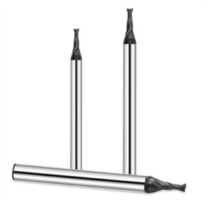
Common Issues in Graphite Milling Machine Setup
In our field projects, processing bottlenecks usually stem from mismatches between machine setup, tooling, and parameter strategies rather than bad raw material. During continuous mass production, subtle issues—like fine dust accumulation, premature edge wear, or deep-cavity chatter—slowly degrade overall yield and drive up scrap rates.
When troubleshooting production issues, start by analyzing physical shop-floor phenomena before overhauling your entire manufacturing strategy. Examining machine condition, workpiece geometry, and tool wear patterns under magnification reveals whether the fix requires simple parameter tweaks or machine reconfiguration.
Why Does CNC Graphite Machining Generate Excessive Dust?
Graphite milling inherently produces fine abrasive dust, but uncontrolled airborne particulates point directly to poor vacuum setups and inadequate seals. Standard CNC machines lack specialized dust collection systems, allowing airborne micro-particles to settle inside spindle tapers, linear guides, and way covers, eventually destroying axis positioning accuracy.
To resolve dust issues during CNC graphite machining, inspect vacuum air volume, shroud proximity, and enclosure seal integrity. Cutter geometry and parameter selection also dictate dust particle size and flight paths. Implementing an optimized dust extraction setup protects sensitive machine internals while maintaining operator safety and process repeatability.
How to Optimize Graphite Machining Speed and Feed for Longer Tool Life?
A common mistake on the shop floor is assuming that simply cranking up RPM and feed rates boosts throughput. If parameters exceed tool geometry limits or machine rigidity, the cutter suffers severe flank wear and impact micro-chipping, ruining part surface finishes.
Finding the ideal graphite machining speed and feed involves balancing spindle speed, chip load per tooth, and depth of cut against your specific machine setup. Log tool wear progression, cycle times, and CMM dimensional data during initial parameter runs to dial in the sweet spot for your material grade.
When Should You Use a Long Neck Graphite End Mill for Deep Cavity Machining?
Deep electrode cavities create constant interference risks and tool deflection challenges. Standard end mills lack the reach needed for narrow slots and complex 3D contours, forcing operators to run excessive tool overhangs that induce destructive chatter.
Using a specialized long-neck graphite end mill allows tools to reach deep cavity floors safely without sacrificing neck strength. Always evaluate your reach-to-diameter ratio and machine rigidity before selecting a neck length; keeping the tool overhang as short as possible ensures maximum cutting stability and tight dimensional control.
How Does Diamond Coating Improve Graphite Milling Performance?
Abrasive wear from micro-fine graphite dust rapidly dulls uncoated carbide edges, causing dimensional drift and heavy edge burrs. A specialized CVD diamond coating creates an extremely hard protective barrier that resists micro-abrasion during extended, high-speed milling passes.
In high-volume or tight-tolerance electrode jobs, diamond-coated end mills dramatically extend tool life and hold tight tolerances. However, coating effectiveness depends heavily on carbide substrate bonding and proper cutting parameter matching. Always test diamond coatings under real production conditions to confirm your tooling ROI.