


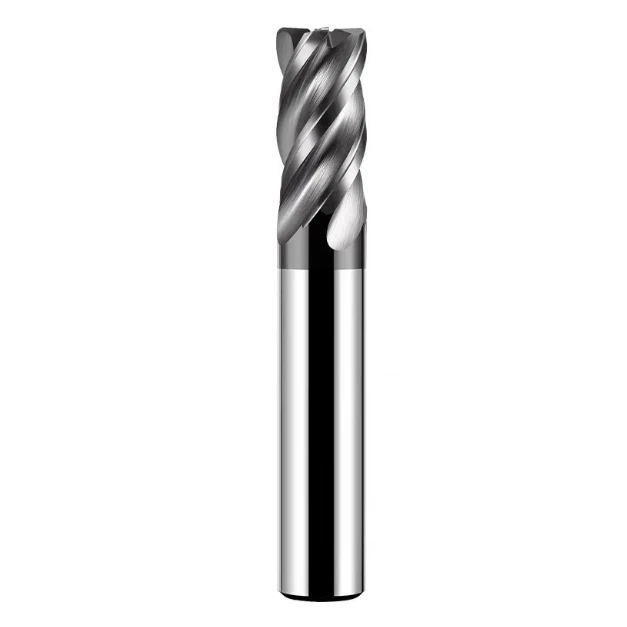
Last month, a long-standing US client emailed us about a severe bottleneck. While machining large 4140 pre-hardened steel hydraulic valve blocks (HRC 35–38), their cycle times doubled, and sudden tool chipping repeatedly halted the production line.
This scenario represents a classic workshop issue we have resolved across the US and Europe for over a decade. Many shops instinctively search online for the best endmill for steel, expecting a magic bullet. However, as hands-on tool manufacturers, we know no single cutter fits every steel milling application.
For heavy stock removal, prioritizing chip evacuation and minimizing spindle load is essential for profit margins. Deploying a dedicated roughing endmill for steel during this phase delivers the high Metal Removal Rate (MRR) you need. For subsequent semi-finishing and complex profiling, switching to a bullnose endmill for steel prevents corner failure and ensures optimal surface finishes.
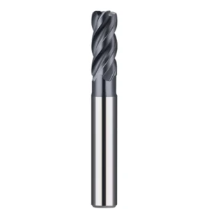
Deep-cavity hard milling above HRC 55 introduces an entirely new level of difficulty where standard tooling fails. In these setups, you must run a specialized hrc55 4flutes solid carbide long neck end mill with high-rigidity clearance design. Paired with MQL or air blast, these tools reach deep pockets safely without snapping.
Beyond programming strategies, shop supervisors must closely vet their upstream supply chain logistics. While the market features countless carbide endmill suppliers, few can guarantee consistent substrate grain quality and coating adhesion. Buying cheap tools made from recycled carbide always costs more due to premature failure and scrap.
Therefore, this technical guide skips dry textbook theories to focus on real-world machining data and shop floor experiences. When running challenging steel jobs, have you ever watched your profits vanish into the chip hopper just because you selected the wrong cutter?

Why We No Longer Argue with Western Clients About the “Best Endmill for Steel”
Over the past decade of working with process engineers and purchasing managers in Western shops, we frequently get inquiries looking for the absolute “best endmill for steel.” Ten years ago, we might have scrambled to present laboratory reports on coating hardness and substrate strength to prove our worth. Today, as tool manufacturers dealing with daily cycle times and machine rigidity, we no longer engage in such futile debates.
The reality of metal cutting is that there is no “universal super-tool” capable of handling every type of steel part. For a German production supervisor, “best” might mean exceptional consistency for unattended weekend runs. For a fast-paced American job shop, it means stripping stock rapidly at high feed rates without edge failure. Discussing tools in isolation—without considering hardness, spindle power, and workholding—is simply unprofessional.
Starting with the Shop Floor Bottom Line: Balancing MRR and Tool Life
On the shop floor, every second a spindle runs carries a direct cost. We often walk customers through a simple calculation: do you want a tool that cuts continuously for five hours at conservative parameters, or a solution that strips away all the metal in two hours—even if it requires a tool change halfway through? This highlights the constant trade-off between Metal Removal Rate (MRR) and tool life.
Too often, supervisors lower feed rates to save a few dollars on tooling, only to see machine-hour costs skyrocket. We always recommend identifying your project’s core bottleneck before selecting your tooling. For heavy-stock roughing, push your removal efficiency to the limit; during finishing, prioritize thermal shock and wear resistance to keep your dimensional tolerances tight.
How We Helped a US Automotive Mold Shop Cut Machining Time by 35% Through Tool Selection
Last year, a process supervisor at a Detroit automotive mold shop approached us while machining complex interior molds made from P20 pre-hardened steel. Due to deep cavities and tight corners, they used standard long-neck flat-bottom tools for semi-finishing. However, the excessive length-to-diameter ratio caused severe tool deflection at higher feed rates, resulting in chatter marks that required hours of manual polishing.
After analyzing their CAM toolpaths, we recommended switching to a bullnose endmill for steel optimized for contouring, paired with an air-cooling strategy for deep slots. The corner radius geometry redirected cutting forces axially, instantly eliminating tool deflection and resonance. Ultimately, the surface finish met “polish-free” standards, and the total machining time per part was reduced by 35%, rescuing their delivery margins.
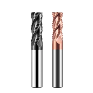
When Should You Prioritize a Roughing End Mill for Steel? Limits and Pitfalls of Heavy-Duty Roughing
When machining steel, many operators try to save tool change time by using a single standard flat-bottom tool from roughing to finishing. However, when hogging out large amounts of material from a solid block, this approach drastically accelerates tool wear and drives up costs. In these high-volume scenarios, a specialized roughing endmill for steel is your best asset for boosting shop output.
The goal of roughing is to strip away excess metal quickly; what matters is chip evacuation and edge toughness, not surface finish. When we optimize processes, we always look at the chips. If they are blue-tinted, uniform, and the spindle load is stable, your parameters are in the sweet spot. If your shop spends over 30% of its time on slow “scraping,” you need to switch to heavy-duty roughing.
Choosing Between Serrated and Flat Edges: Lessons Learned the Hard Way About Tool Breakage in High-Hardness Steel Roughing
In our early days, we paid a heavy price for poor tool geometry choices when machining H13 hot-work die steel (around HRC 48–50). Driven by a desire for “universal compatibility,” we stubbornly used flat-edge tools for heavy roughing, only to hear the sharp snap of broken carbide every few parts. Flat edges engage hardened steel abruptly across the entire cutting edge, triggering thermal fatigue and micro-chipping.
We solved this by switching to a roughing endmill for steel featuring a serrated wave-edge design. The serrations break wide chips into small, manageable fragments, which drastically reduces cutting resistance. Although this leaves a stepped, wavy finish that requires a semi-finishing pass, the process security it offers in hardened steel is unmatched by standard flat-edge designs.
Maximizing Roughing Endmill Potential with High-Efficiency Dynamic Milling (HEM)
Traditional cutting methods with full radial engagement and shallow axial depths are being replaced by High-Efficiency Dynamic Milling (HEM). HEM uses deep axial cuts (large ap) and very small step-overs (small ae) to distribute cutting heat evenly along the entire flute length. To harness this programming method, your roughing endmill for steel must feature excellent thermal shock resistance.
In practice, we often see programmers run dynamic toolpaths with conservative feed rates, which causes rubbing and rapid tool burnout. When running HEM, we recommend aggressive feed-per-tooth (Fz) rates. Because the engagement angle is tiny, you can significantly increase both spindle speed and feed rate. When chips fly off smoothly like dry cereal, you have maximized the tool’s potential.
Shop-Floor Challenges: Solving Spindle Vibration and Chatter During Heavy-Duty Roughing
The low-frequency rumbling and piercing screech of chatter during heavy steel roughing is a nightmare for any operator. Chatter destroys cutting edges and inflicts irreversible mechanical damage on your machine’s spindle bearings. We once assisted a client whose #30 taper spindle vibrated so violently during roughing that water cups shook on the console; in this scenario, buying more expensive tools rarely helps.
Our engineers resolved this by upgrading their old collet chucks to high-rigidity shrink-fit holders, reducing radial runout to under 0.003mm. We then programmed the job using roughing cutters with unequal flute spacing and variable helix angles. This asymmetrical geometry breaks up harmonic resonance cycles during cutting, eliminating chatter and turning a violent vibration into a smooth, reliable cut.
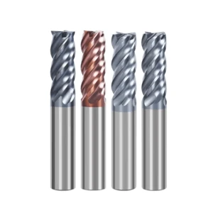
When Must You Switch to a Bullnose Endmill for Steel? Golden Rules for Preventing Chipping and Handling Curved Surfaces
After heavy-stock roughing, shops often face a tough choice when moving to semi-finishing: stick with a sharp-edged flat tool or switch to a ball-nose cutter? We frequently see operators take shortcuts by running standard flat tools on steep steel slopes, only to watch the corners instantly chip. During this high-stress finishing stage, switching your setup to a dedicated bullnose endmill for steel is the absolute key to protecting your tool and keeping your tolerances tight.
This corner-radius design is specifically engineered to handle the brutal cutting stresses of steel machining. Its geometry distributes cutting forces evenly across the radiused edge, preventing micro-chipping at what would otherwise be a vulnerable 90-degree sharp point. Whether you are profiling complex 3D surfaces, finishing cavity sidewalls with transition radii, or running high-feed floor passes, a bullnose tool makes your setup run smoother and infinitely more reliably.
16 Years of Process Expertise: Why a Corner Radius Can Save Your Finishing Tools
Based on our years on the shop floor, when standard flat carbide tools cut hard steel, the sharp 90-degree corners are always the first to go. Microscopic analysis shows that most flat tool failures are caused by impact-induced fatigue chipping at the corner, which quickly ruins the entire cutting edge. We once ran tests for a client showing that simply swapping a sharp corner for an R0.5 or R1.0 radius increased tool life by two to three times under identical parameters.
This corner radius physically reinforces the structural integrity of the cutting edge. It also alters force vectors, converting radial deflection forces into axial forces directed straight up the machine spindle, which drastically reduces chatter. When machining tough alloy steels or pre-hardened tool steels, do not blindly demand a perfect 90-degree corner. If blueprint tolerances allow, ask your carbide endmill suppliers for a small corner radius to immediately save your finishing tools.
Efficiency Advantages of Bullnose End Mills Over Ball Nose End Mills in Cavity Corner Cleaning and 3D Surface Semi-Finishing
In mold shops, many programmers habitually grab a ball-nose tool for 3D semi-finishing and bottom corner cleaning. While ball-nose tools are vital for dramatic, contoured surfaces, they are highly inefficient in shallow cavities with flat bottoms and slight wall angles. This is because the cutting speed at the very center of a ball-nose tip approaches zero during rotation, meaning the material is actually extruded rather than cut, causing rapid tool wear.
Using the right bullnose endmill for steel offers an unmatched efficiency advantage in these specific zones. The flat bottom face of the bullnose cutter wipes the floor clean at high speed, while the corner radius smoothly blends the floor to the wall. This allows you to program a much wider stepover than a ball-nose tool would allow, effectively doubling your metal removal rates without sacrificing any geometric accuracy.
Achieving Near-Mirror Surface Finish on Stainless and Alloy Steels by Optimizing Bull-Nose End Mill Parameters
When machining tough, gummy alloys like stainless steel or chromoly, getting a clean surface roughness (Ra) value is a major bottleneck. Many shops rely entirely on slow, manual hand-polishing, which ruins part geometry and inflates your labor costs. While cutting stainless parts for a medical device contract, we hit a polish-free surface finish right off the machine by precisely tuning our bullnose cutting parameters, earning a major win with the client’s engineering team.
The secret is balancing your feed per tooth directly against the corner radius. Your chip thickness must be thin enough to prevent built-up edge (BUE) but thick enough to avoid rubbing, which causes work hardening. We recommend running a high cutting speed (Vc) to let the coating’s thermal barrier protect the edge, while matching your feed rate to keep your theoretical scallop height in the micron range. Paired with high-pressure air, it yields an incredible metallic luster.
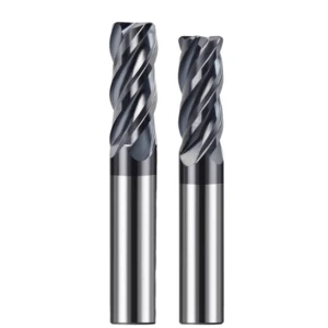
Tackling the Challenges of HRC55+ Hardened Steel: Why We Recommend Neck-Relief End Mills
Once workpiece hardness crosses the HRC 55 threshold, the physics of chip formation change completely. We often see supervisors new to hard milling try to machine hardened tool steel with standard carbide tools, resulting in immediate edge burnout or the tool shattering into powder. HRC 55+ materials generate intense localized heat and exhibit high yield strength, requiring extreme hot hardness, advanced coatings, and specialized tool geometries.
In our technical support projects, Western engineers frequently struggle with tool interference and deflection when milling deep pockets or narrow ribs. Standard long-flute tools create too much contact area in hard metals, triggering massive cutting forces and chatter. We strongly recommend using a neck-relief tool design. By shortening the cutting edge and relieving the neck, you secure the deep reach you need while eliminating friction and rubbing.
Why Do You Need an HRC55 4-Flute Solid Carbide Long Neck End Mill for Deep Cavity Machining?
Machining deep-cavity molds in hardened steel presents an inherent conflict between cavity depth and tight working clearance. Running a standard flat-bottom tool leads to heavy rubbing against the cavity walls, and poor chip evacuation causes chips to be recut at the bottom, snapping the tool. This is why you need a specialized hrc55 4flutes solid carbide long neck end mill to safely navigate these deep, narrow spaces.
Engineered for hard milling, the neck relief of this tool easily clears cavity walls while its 4-flute layout provides excellent rigidity for finishing. Because hardened steel produces tiny, highly abrasive chips, the 4-flute design balances chip pocket space with superior edge strength compared to 2- or 3-flute options. When cleaning corners in hardened mold steel, this design delivers dimensional stability and wear resistance that standard tools simply cannot match.
Addressing the Critical Issue of “Tool Deflection” with Long Neck Relief Cutters: Our Solutions in Programming and Workholding
While long-neck tools solve cavity interference, they suffer from a major physical drawback: tool deflection caused by high length-to-diameter ratios. When a tool overhangs too far, even light cutting forces bend the neck, causing chatter marks and dimensional errors, or snapping the tool upon spring-back. Many shops blindly lower their spindle speeds when they see deflection, which actually increases cutting forces and accelerates tool failure.
To resolve deflection, we combine rigid workholding with smart programming. First, ditch standard spring collets in favor of high-quality shrink-fit or hydraulic tool holders to keep your runout under 0.003mm. On the programming side, use CAM paths like trochoidal milling or helical ramping that utilize low radial engagement and high feed rates. This reduces radial cutting forces and directs the load axially up the spindle.
Rigidity Performance of 4 Flutes Solid Carbide Tools in Hard Milling
In hard milling, the rigidity of your tool material dictates whether your project succeeds or fails. We always emphasize that when cutting hardened steel, the structural advantages of a hrc55 4flutes solid carbide long neck end mill are irreplaceable. The ultra-fine micrograin carbide substrate provides the extreme hardness and flexural strength required to survive the initial impact of engaging hardened tool steel without chipping.
On the machine, 4-flute solid carbide tools maintain a highly stable cutting load even at elevated surface speeds. This structural stiffness suppresses micro-chipping and prevents the tool from deflecting when hitting areas of inconsistent material hardness. When you hear that deep, steady hum from the spindle, you know your tool is rigidly performing its job and securing a reliable finish on your hardest workpieces.

As Engineers, How Do We Help Western Buyers Vet Qualified Carbide End Mill Suppliers?
Over more than a decade of collaborating with manufacturing shops in Europe and the US, we have hosted countless overseas buyers arriving with strict procurement lists. When vetting carbide endmill suppliers, many purchasing managers fall into the trap of focusing solely on upfront price comparisons and glossy catalogs. However, as engineers with decades of hands-on machining expertise, we know that cutting tools are a fundamental pillar directly determining shop productivity, not just cheap consumables.
If a supplier only understands sales but lacks real-world knowledge of metal-cutting dynamics, you pay the price later. Any quality fluctuations during mass production will translate directly into scrap parts and costly spindle downtime. Evaluating a partner requires looking past promises made at a conference table to audit their actual technical expertise and batch-to-batch quality control systems.
Look Beyond the Sample: The Hidden Reality of Carbide Substrate Grain Size and Coating Consistency
In B2B procurement, buyers are often impressed by the flawless “golden samples” sent for initial evaluation, only to see tool life plummet once production begins. Maintaining consistent quality during high-volume assembly line production is the true test of a manufacturer. At our facility, every incoming batch of raw rod stock undergoes strict metallurgical microscope inspection to verify grain size and uniform cobalt distribution.
Another critical factor that dictates performance is coating consistency across high-volume production batches. To cut corners, some budget suppliers use outdated physical vapor deposition (PVD) furnaces or skip crucial pre-cleaning steps, leading to poor adhesion. This causes the coating to flake off extensively after less than ten minutes of actual steel cutting, destroying the substrate.
Why Top Suppliers Must Have the Capability to Deliver “Non-Standard Customization” and “Technical Parameter Support”
In real-world machining, off-the-shelf standard tool dimensions cannot solve every complex manufacturing challenge. We frequently collaborate with European and American clients facing component bottlenecks like undercut interference, deep-pocket clearance limits, or specific radius transitions. If your tooling partner is merely a standard trading company or a low-end manufacturer lacking an independent R&D department, they cannot support these non-standard requirements.
A truly capable engineering partner can analyze your CAD drawings to rapidly calculate optimal neck clearance, flute-to-length ratios, and custom variable helix angles. More importantly, custom tools are useless without dedicated technical support. When we deliver a custom geometry, our team provides tailored feed-per-tooth, cutting speed, and toolpath recommendations to ensure the tool performs perfectly the moment it hits your spindle.
How to Avoid the Hidden Pitfalls of Recycled Carbide When Purchasing Carbide End Mills In Bulk
There is a major open secret in the manufacturing industry regarding the massive performance gap between virgin tungsten substrate and recycled carbide. The vast majority of ridiculously cheap milling cutters flooding the market are manufactured by re-melting and regrinding scrap tool matrixes. While they appear identical to premium tools on the surface, this recycled material is riddled with micro-impurities and inconsistent grain boundaries.
This structural degradation causes a drop in transverse rupture strength (TRS) of over 30%, making the tools highly susceptible to sudden, brittle failure under load. To avoid this trap, ask your carbide endmill suppliers for material certificates for the raw rod stock. Proactively verifying that your partner uses premium, ultra-fine-grain virgin carbide is the most effective procurement strategy to lower your total cost per part.
Recommended Practical Cutting Parameters (For Medium-Carbon Steel, Alloy Steel, and Pre-hardened Steel)
On the shop floor, even the most advanced tool geometry and coating technology are useless without the right cutting parameters. Over the years, we have witnessed countless cases where high-end tools were worn to death by conservative parameters or chipped by aggressive settings. The benchmark data outlined below does not represent idealized laboratory findings, but rather practical threshold values proven through extensive field testing in our clients’ shops.
No single set of speeds and feeds can be applied blindly to every single machine tool setup. Factors like spindle rigidity, fixture stability, and the dynamic balance of your tool holder drastically alter your cutting results. We provide this baseline to help you benchmark your operations. If you encounter abnormal chatter, comparing your setup against these practical parameters will help pinpoint optimization opportunities.
Recommended Feed and Depth of Cut (Ap/Ae) for Roughing Endmills
If you are using a professional roughing endmill for steel to hog out large amounts of stock, try adopting our recommended “large axial, small radial” cutting strategy. For standard 4140 or 8620 alloy steels, we suggest boldly setting your axial depth of cut (Ap) between 1.5D and 2D. Concurrently, you must strictly control the radial depth of cut (Ae) between 0.1D and 0.15D to manage heat.
When paired with modern dynamic milling toolpaths, your feed per tooth (Fz) can generally range from 0.08 mm/t to 0.15 mm/t. If you notice poor chip evacuation or chip packing at the bottom of a pocket, try slightly reducing the radial engagement while bumping the feed rate by 20%. This thins the chip and forces smooth, high-speed evacuation out of the cut zone.
Cutting Speed (Vc) and Feed per Tooth (Fz) for Optimal Surface Finish with Bullnose Endmills
If you are preparing to run a final finishing pass with a bullnose endmill for steel, you can hit a mirror-like finish by fine-tuning your speed and feed balance. When machining pre-hardened mold steels like NAK80 or P20, we recommend maintaining a high cutting speed (Vc) of 120–180 m/min. This thermal load activates the coating’s oxidation resistance, protecting the corner radius from abrasive wear.
To minimize your scallop height, keep your feed per tooth (Fz) tightly controlled between 0.03 mm/t and 0.06 mm/t. When profiling slight angles, this allows the corner radius to create uniform, micron-level wiping marks across the workpiece. Provided your spindle runout is under 0.005 mm, this parameter mix can eliminate hours of tedious manual hand-polishing.
Dry/Air Cooling vs Wet Cutting: Cooling Strategy Recommendations for Various Steels
There is a long-standing debate on the shop floor regarding whether to run flood coolant or dry air when cutting steel. Our field experience shows that if you are hard-milling materials above HRC 55—especially when using a hrc55 4flutes solid carbide long neck end mill—you must avoid liquid coolant entirely. Switch to high-pressure dry air or Minimum Quantity Lubrication (MQL) to prevent thermal shock.
The intense localized heat of hard milling means intermittent liquid cooling causes the cutting edge to undergo violent thermal expansion and contraction. This triggers micro-cracking along the tool edge, leading to instant catastrophic chipping. Conversely, if you are machining gummy low-carbon steels or stainless steel, run high-pressure flood coolant or through-spindle emulsion to drop the cutting zone temperature and flush out sticky chips.






