


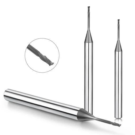
During a high-precision graphite electrode machining project, a customer ran into a recurring issue. The process ran smoothly for the first few hours using standard graphite end mills. However, as cutting depth increased, slight edge chipping appeared, dust generation spiked, and tool life dropped sharply.
The team initially adjusted spindle speed, feed rate, and depth of cut without success. A detailed wear and cutting force analysis revealed the actual root cause: an improper graphite end mill helix angle.
Many machine shops focus primarily on substrate grades, diamond coatings, and flute counts while overlooking helix geometry. For brittle materials like graphite that fracture under impact, the graphite end mill helix angle directly dictates cutting force distribution, dust evacuation, and part integrity.
An optimized helix angle balances axial and radial cutting forces during high-speed milling. When paired correctly with rake and clearance angles, it minimizes tool deflection, prevents micro-chipping on delicate ribs, and eliminates surface burrs.
In precision electrode fabrication, an inappropriate helix angle increases cutting impact and chatter. This instability accelerates abrasive wear, generates excess airborne dust, and degrades tight dimensional tolerances.
A dedicated graphite end mill design dampens cutting vibration and channels abrasive particles efficiently away from the cut zone. This structural stability keeps cutting temperatures low and protects delicate workpiece corners throughout extended production runs.
For demanding applications like semiconductor graphite components and fine-pitch EDM molds, tool performance requires an integrated approach. We pair optimized helix geometries with multi-layer diamond coatings to handle the extreme abrasiveness of ultra-fine grain graphite.
Optimizing tool geometry alongside durable coatings extends tool life, stabilizes high-speed machining, and ensures consistent surface finishes. A targeted graphite end mill helix angle design solves long-standing edge-chipping issues and keeps your CNC operations profitable.
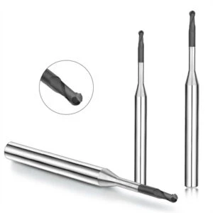
Graphite End Mill Helix Angle Basics: How Helix Geometry Impacts CNC Graphite Machining
In precision graphite electrode machining, machinists often adjust spindle speeds and feed rates while overlooking cutting tool geometry. During high-speed operations, the tool helix angle directly dictates cutting force distribution, dust clearance, and edge stability. Proper tool design protects delicate electrode ribs far better than simply modifying machine parameters.
Graphite is an abrasive, brittle material that chips easily under excessive impact. Selecting the right helix angle requires balancing cutting edge sharpness, core rigidity, and machine tool dynamics. An optimal tool geometry minimizes cutting vibration while preventing premature micro-fracturing along workpiece edges.
Understanding the Graphite End Mill Helix Angle
The graphite end mill helix angle is the angle formed between the cutting edge and the tool’s centerline axis. This angle controls how cutting forces divide into radial and axial directions as the flute engages the graphite. Lower helix angles offer stronger edge support for stable cutting, while higher angles provide a smoother shearing action.
A successful tool profile balances the helix angle with rake angles, relief clearance, and flute volume. Even high-grade carbide with diamond coating will chip if the tool geometry causes excessive cutting shock. We evaluate the complete tool architecture to ensure the helix angle delivers stable machining accuracy and long-term durability.
Controlling Cutting Forces and Chip Evacuation
High-speed graphite milling produces fine, abrasive dust that must evacuate quickly from the cutting zone. If graphite particles pack into the flutes, secondary rubbing accelerates abrasive flank wear and degrades surface finishes. Monitoring dust flow during test cuts provides clear feedback on whether the flute geometry is performing efficiently.
An optimized graphite milling helix angle guides fine particles smoothly along the flutes to prevent dust buildup. In dry high-speed milling, efficient chip evacuation maintains lower cutting temperatures and extends tool life. Combining correct helix geometry with adequate dust extraction keeps cutting forces consistent across long machining cycles.
Performance Differences Across Helix Angle Configurations
Different graphite grades and feature geometries demand specific tool designs. Fine-detail electrode finishing requires maximum cutting stability to protect thin walls, whereas heavy roughing requires open flutes and smooth shearing for bulk material removal. No single tool configuration fits every graphite milling stage.
Achieving tight tolerances in CNC graphite machining requires matching the helix angle with tool diameter, flute count, and diamond coating quality. Selecting cutting tools based on specific graphite grain structures and cavity depths ensures repeatable part accuracy. Proper geometric alignment delivers cleaner cuts, lower tool wear, and dependable production runs.
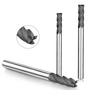
Optimizing Graphite End Mill Design: The Relationship Between Helix Angle and Tool Structure
Using identical CNC machines and parameters with different tools often produces drastically different outcomes. While one cutter produces smooth surfaces and stable passes, another causes edge chipping, chatter, or premature dimensional drift. These performance gaps rarely stem from feeds and speeds alone, but from the cutter’s underlying structural geometry.
A successful graphite end mill design balances the helix angle, flute count, core diameter, and edge preparation into a cohesive system. Because graphite is prone to micro-fracturing and heavy dust generation, tool geometry must combine cutting sharpness with rigid support. This structural synergy prevents edge blowout and stabilizes long production runs.
Balancing Helix Angle, Flute Count, and Flute Geometry
Helix angle, flute count, and chip clearance space are deeply interconnected parameters. Adding flutes increases feed rates and rigidity, but reduces the flute valley volume needed for abrasive dust evacuation. An optimized helix angle guides fine particles away from the cut zone, preventing dust packing and secondary edge rubbing.
For deep-cavity EDM electrodes, tool designs must prioritize flute clearance and harmonic damping to avoid deflection. For bulk material removal, balancing tool core thickness with open flutes provides the strength needed for higher chip loads. Matching flute geometry to the specific depth of cut maintains clean shearing and extended tool life.
Performance Differences: High-Helix vs. Low-Helix Graphite End Mills
High-helix graphite end mills (typically 35° to 45°) ensure smoother entry, lower cutting impacts, and reduced vibration. These characteristics make them ideal for delicate finishing passes and achieving superior surface roughness on thin-rib electrodes. However, the steeper edge profile requires a premium micro-grain substrate to prevent edge breakdown under heavy loads.
In contrast, low-helix designs (20° to 30°) maximize radial core rigidity and edge strength. They provide exceptional stability when machining highly abrasive, coarse-grained graphite or performing interrupted cuts. Selecting between high- and low-helix tools depends strictly on workpiece geometry, cavity depth, and machine tool rigidity.
Enhancing Graphite Machining Accuracy Through Tool Geometry
Maintaining tight tolerances across multiple graphite parts is a common challenge in electrode manufacturing. Dimensional drift often occurs when progressive tool wear alters the cutting forces, causing the tool to deflect. Standard cutter geometries frequently struggle to sustain uniform cutting action over long, unattended machining cycles.
Fine-tuning the helix angle alongside the rake angle, relief clearance, and edge hone evenly distributes cutting loads. This structural balance dampens vibration and prevents graphite micro-breakout, directly improving graphite machining accuracy. Pairing optimized tool geometry with diamond coatings guarantees repeatable precision from the first part to the last.
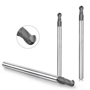
Selecting the Helix Angle for Graphite Milling: Optimization Strategies for Various Machining Scenarios
Machinists often wonder why a single end mill excels during roughing but struggles during finishing or deep-pocket milling. In CNC graphite machining, this performance drop rarely comes from incorrect feeds or speeds. Instead, it stems from a mismatch between the cutter’s geometry and the specific stage of the machining cycle.
Graphite milling covers diverse demands, from high-volume bulk removal to delicate, thin-rib electrode contouring. Each operation requires a dedicated balance of edge strength, harmonic damping, and dust evacuation. Selecting the right graphite milling helix angle requires matching tool geometry to graphite grain size, part overhang, and machine rigidity.
Helix Angle Design for Graphite Roughing
Roughing focuses on high material removal rates (MRR) and cutting edge durability under heavy chip loads. Using a high-helix finishing tool for aggressive bulk milling often leads to severe tool chatter and dust packing. These issues accelerate abrasive flank wear and jeopardize process stability.
For bulk roughing, lower to moderate helix angles (25° to 30°) provide maximum core rigidity and edge toughness. This geometry directs cutting forces into the spindle, dampening vibrations and resisting shock loads on interrupted cuts. Optimizing roughing geometry balances high productivity with dependable tool life and process safety.
Helix Angle Requirements for Graphite Finishing
Graphite electrode finishing prioritizes exceptional surface finish, sharp edge definition, and sub-micron dimensional repeatability. An improper finishing cutter can leave visible feed lines or trigger micro-chipping along delicate electrode ribs. These small imperfections degrade EDM spark performance and lead to costly scrap.
Precision finishing requires higher helix angles (35° to 45°) to provide a continuous, low-impact shearing action. This gentle cutting motion reduces tool deflection and prevents brittle breakout on thin walls. Matching helix geometry with diamond coatings ensures uniform cutting forces and exceptional graphite machining quality.
Impact of Helix Angle on Deep-Cavity Electrode Machining
Deep-cavity electrode machining presents tough challenges due to long tool overhang and reduced system rigidity. Extended-reach tools are highly prone to deflection, harmonic vibration, and poor dust clearance. In deep pockets, trapped graphite dust causes severe secondary abrasive wear on the cutter.
Deep-cavity milling demands a specialized helix angle paired with an expanded flute valley and reinforced core. This structure pulls abrasive dust upward while suppressing harmonic chatter at long gage lengths. Optimizing tool architecture maintains dimensional accuracy across deep vertical walls without requiring manual polishing.
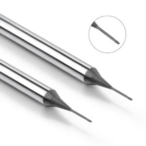
The Impact of Graphite End Mill Helix Angle on Machining Quality
In high-volume graphite electrode manufacturing, quality defects often develop gradually rather than appearing immediately. During a mold electrode production run, early parts came out cleanly, but slight edge chipping and micro-fractures emerged after a few hours of operation. Investigating the tool wear patterns revealed that an mismatched helix angle was causing excessive cutting shock as the edge dulled.
Graphite is brittle and extremely sensitive to sudden mechanical impact. If tool geometry fails to balance cutting forces, the material breaks away in ragged micro-cracks rather than shearing cleanly. Designing a high-performance graphite end mill helix angle ensures smooth material entry, stable chip evacuation, and reliable edge protection across long machining cycles.
Optimizing the Helix Angle to Reduce Graphite Machining Burrs
A common misconception is that brittle graphite cannot form burrs like metals do. In practice, improper cutting action leaves ragged edge breakouts, fuzzy micro-burrs, and damaged rib corners. These defects stem from uneven cutting force distribution and abrasive edge degradation during high-speed passes.
An optimized helix angle creates a progressive slicing action that significantly reduces exit impact on delicate features. Distributing cutting loads evenly along the flute minimizes the risk of graphite machining burr formation on sharp corners. This structural optimization eliminates manual deburring and protects fragile electrode ribs.
How the Helix Angle Improves Graphite Machining Quality
Surface finish degradation does not always mean spindle speeds or feed rates are incorrect. Using the exact same cutting parameters with different tool geometries produces noticeably different surface textures and dust flow patterns. Tool geometry directly controls harmonic stability and chip clearing behavior.
An engineered helix angle dampens machining chatter and prevents fine dust from packing into the cut zone. Prompt particle evacuation stops abrasive graphite dust from re-cutting against the relief walls and wearing the diamond coating prematurely. This smooth cutting action delivers dependable graphite machining quality across intricate electrode contours.
Enhancing Graphite Machining Accuracy Through Helix Geometry
Maintaining tight dimensional tolerances is critical when machining precision EDM electrodes in batches. Unstable cutting forces cause the tool to deflect, resulting in tapered side walls and dimensional drift across multi-part production runs. A mismatched helix angle accelerates this deflection by generating uncontrolled lateral cutting loads.
Balancing the helix angle directs cutting forces along the tool axis, maximizing overall rigidity and edge retention. Combining optimized helix geometry with tough carbide substrates and diamond coatings keeps tool deflection minimal during continuous cuts. This structural stability secures reliable graphite machining accuracy and cuts costly rework.
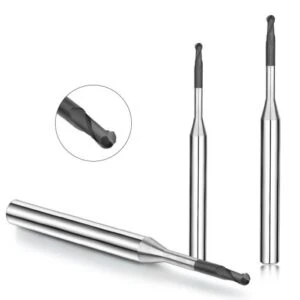
Graphite End Mill Tool Life Analysis: How Helix Angle Affects Cutter Longevity
Machinists often ask why tools with identical specs show vastly different lifespans under varying operating conditions. While one cutter machines dozens of electrodes reliably, another suffers premature flank wear, edge dulling, and acoustic chatter after just a few parts. These rapid failures usually stem from underlying geometric mismatches rather than faulty carbide.
Tool longevity depends on how tool geometry balances mechanical loads with material behavior. An improper helix angle increases localized cutting resistance and traps abrasive dust in the cut zone. Analyzing how geometry distributes cutting forces allows shops to prevent premature edge breakdown during demanding production runs.
Helix Angle, Cutting Resistance, and Abrasive Tool Wear
Inspecting wear lands under a toolmaker’s microscope reveals whether cutting forces are evenly distributed along the edge. Although graphite is soft, its abrasive grain structure exerts continuous micro-impacts that induce edge fatigue. Concentrated cutting loads accelerate micro-chipping on the relief face and strip protective coatings prematurely.
The helix angle dictates how cutting resistance splits between axial and radial directions. An optimized entry angle cushions initial material contact, dampening shock loads and protecting cutting edges against fatigue. Aligning helix geometry with material grain size significantly extends graphite end mill tool life.
Causes of Rapid Tool Failure from Incorrect Helix Angles
Pushing feed rates without optimizing tool geometry often triggers rapid tool failure. In a mold electrode project, an aggressive feed increase caused sudden edge collapse because the helix angle could not handle the increased radial load. Unbalanced cutting forces concentrate stress at the tool corner, accelerating flank wear.
Poor dust clearance also worsens abrasive tool degradation. When flutes fail to evacuate fine graphite dust immediately, trapped particles pack into the cut zone and grind against the tool coating. Matching the helix angle to pocket depth and vacuum extraction keeps flutes clear and prevents excessive frictional heat.
Optimizing Graphite End Mill Design to Maximize Longevity
Maximizing cutter durability requires harmonizing the helix angle, core thickness, flute count, and cutting edge hone into a balanced system. Roughing requires reinforced core profiles and open flutes for chip evacuation, while finishing tools prioritize low-impact shearing for edge preservation. Tailoring cutter design to the specific milling stage prevents erratic wear patterns.
A well-engineered graphite end mill design pairs optimized helix geometry with a high-adhesion CVD diamond coating for maximum abrasive resistance. Balanced cutting action stabilizes tool deflection and prevents coating delamination under high-speed conditions. Aligning tool architecture with machining parameters delivers predictable cutter longevity and reliable production output.
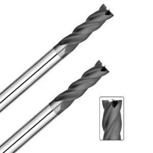
Diamond-Coated Graphite End Mill Design: Synergistic Optimization of Helix Angle and Coating Performance
Shops often switch to diamond coatings hoping to instantly solve tool wear issues, but coating alone cannot overcome poor geometry. In high-speed milling, some users still experience edge chipping, poor dust clearance, and inconsistent finishes despite using expensive coatings. A premium coating cannot compensate for high cutting shock or poor chip evacuation.
Cutter performance relies on the synergy between the carbide substrate, edge preparation, flute polish, and helix angle. Graphite’s abrasive nature demands a structural design that complements the physical properties of the coating. Aligning cutter geometry with the coating layer prevents premature edge fracture and ensures stable high-speed passes.
Why Diamond-Coated Graphite End Mills Excel in High-Speed Machining
High-speed machining generates severe abrasive friction that rapidly dulls standard carbide tools. In batch electrode production, even minor flank wear alters spark gaps and compromises final part tolerances. Consistent cutting action requires maximum surface hardness paired with excellent thermal dissipation.
Using diamond-coated graphite end mills provides extreme surface hardness and low friction, shielding cutting edges against abrasive carbon particles. However, the coating only performs when flutes clear dust effectively and cutting forces stay balanced. Combining high-grade diamond film with proper tool geometry ensures repeatable precision across long production cycles.
Maximizing Diamond Coating Adhesion Through Helix Angle Design
The helix angle directly affects how cutting forces contact the coated cutting edge. An mismatched helix angle creates high localized impact forces, risking coating delamination and micro-fractures on sharp corners. Smooth material entry cushions initial contact, preserving the protective diamond layer.
Proper helix geometry also accelerates dust extraction, stopping abrasive particles from packing into flute valleys. Clearing dust quickly eliminates secondary rubbing, protecting the coated relief faces from premature scouring wear. This geometric harmony maximizes coating adhesion and maintains sharp edges during deep-pocket machining.
How a Graphite End Mill Manufacturer Optimizes Tool Architecture
Developing reliable graphite tooling requires analyzing real-world shop floor wear patterns rather than relying on clean lab data. Different operations prioritize different goals: some focus on sub-micron electrode accuracy, while others require maximum material removal rates. Custom tool geometry must adapt to the specific grade of graphite and machining method.
An experienced graphite end mill manufacturer engineers the complete tool system from the ground up. This process integrates micro-grain carbide selection, edge honing, helix angle tuning, and CVD diamond deposition into a unified design. Balancing these engineering factors delivers predictable tool life, lower cost per part, and superior surface quality.
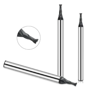
A Graphite End Mill Manufacturer’s Perspective: Designing High-Performance Graphite Machining Tools
Decades of shop-floor experience show that tool performance never depends on a single design parameter. Cutting performance relies on the combined balance between helix angles, flute profiles, core strength, and diamond coatings. When shops face edge chipping, dimensional drift, or short tool life, the root cause is almost always a mismatch between tool geometry and the cut conditions.
As a dedicated graphite end mill manufacturer, we engineer cutting tools around real-world production environments rather than clean laboratory models. We factor in electrode scale, graphite grain size, machine spindle dynamics, and dust collection efficiency before finalizing any cutter profile. Matching the structural geometry directly to your specific application ensures dependable cutting stability and long-term repeatability.
Testing and Optimizing Helix Angles in Tool R&D
Rigorous cutting trials reveal how varying helix angles alter cutting forces, dust extraction rates, and edge wear patterns. Lab tests confirm that no single helix angle fits every graphite milling operation; each cut stage demands distinct geometric trade-offs.
High-speed finishing requires higher helix angles to cushion tool entry and prevent rib blowout on thin electrode walls. In contrast, heavy roughing demands lower helix profiles and thicker cores to absorb heavy cutting shocks without deflecting. Monitoring chatter, dust packing, and wear land progression provides clear guidance on how to optimize cutter geometry for challenging parts.
Tool Structure Insights from CNC Graphite Machining Case Studies
Real-world shop applications demonstrate that solving machining bottlenecks rarely comes from tweaking feeds and speeds alone. In one project, a client suffered severe flank wear during deep-pocket milling and assumed the spindle speed was too high. Our analysis revealed that a narrow flute valley and mismatched helix angle were trapping abrasive dust in the cavity.
Redesigning the cutter with an open flute profile and a balanced helix angle immediately restored smooth chip evacuation and reduced cutting loads. This single geometric adjustment stabilized tool wear and eliminated manual part rework. Analyzing wear marks, cutting harmonics, and dust evacuation paths remains the fastest way to pinpoint root causes in CNC graphite machining.
The Engineering Process for High-Precision Graphite End Mills
Designing high-precision cutters requires a holistic systems approach rather than chasing isolated specs. We combine ultra-fine micro-grain carbide substrates, controlled edge hones, tuned helix angles, and high-adhesion CVD diamond films into a unified cutting tool. This balanced architecture preserves sharp edges while resisting high abrasive friction.
Continuous production feedback allows us to refine our graphite end mill design for high-tolerance mold manufacturing and semiconductor components. Customizing tool geometry to your graphite grade, cavity depth, and machine rigidity delivers consistent dimensional accuracy and extended tool life across every shift.
Frequently Asked Questions: Graphite End Mill Helix Angles
Tool geometry is one of the most debated topics among CNC machinists cutting graphite electrodes. While shops focus heavily on carbide substrates, coatings, and flute counts, optimizing the helix angle is often the missing key when tool life and surface finish hit a plateau.
The graphite end mill helix angle does not work in isolation; it functions alongside material grain size, machine rigidity, and cutting parameters. Below are practical answers to the most common shop-floor questions to help you refine your tooling strategy.
What is the Best Helix Angle for Graphite End Mills?
There is no universal “best” helix angle for every machining scenario. Lower helix angles (25° to 30°) maximize tool core strength and edge rigidity, making them ideal for heavy bulk roughing and abrasive, coarse-grained graphite. Higher helix angles (35° to 45°) deliver smoother shearing action for finishing thin ribs and intricate EDM details.
Selecting the ideal angle requires evaluating your specific graphite grade, cavity depth, and spindle dynamics. Matching the helix angle to the cut stage ensures clean material shearing, dampens harmonic chatter, and maintains tight dimensional tolerances across complex features.
How Does the Helix Angle Affect Graphite Machining Quality?
The helix angle dictates how cutting forces split between the axial and radial directions as flutes engage the workpiece. A well-matched helix angle provides a continuous slicing action that prevents brittle edge breakout and eliminates fine micro-burrs along delicate electrode corners.
Improper tool geometry creates uneven cutting shock and traps abrasive dust in the cut zone, accelerating surface pitting. Upgrading to an optimized helix profile improves dust evacuation paths and dampens vibration, delivering dependable, high-precision graphite machining quality.
Does Helix Angle Design Extend Graphite End Mill Tool Life?
Yes, optimizing the helix angle significantly reduces cutting tool wear by lowering localized impact shock on the cutting edge. Distributing cutting resistance evenly prevents micro-chipping on the relief face, which is the primary cause of premature carbide failure in abrasive materials.
Furthermore, an efficient helix clears fine dust quickly from the flutes, preventing secondary particle re-cutting that scours protective coatings. Maintaining smooth cutting dynamics and proper flute clearance noticeably extends overall graphite end mill tool life.
Are Diamond-Coated Graphite End Mills Always Better?
Diamond coatings provide unmatched surface hardness and abrasion resistance, making them essential for high-speed electrode production. However, a premium coating cannot overcome poor tool geometry; excessive cutting impact or dust packing will chip the edge and delaminate the film regardless of coating quality.
To maximize performance, diamond-coated graphite end mills must combine high-adhesion CVD diamond film with an optimized helix angle and reinforced core. This structural synergy allows the coating to protect the cutting edge throughout long, unattended production runs.
How Do You Choose Tool Geometry for CNC Graphite Machining?
Selecting the right tool geometry requires balancing helix angle, core diameter, flute count, and cutting edge preparation against your operational goals. Roughing requires open flute space and strong cores for rapid chip evacuation, while finishing calls for high-helix flutes and sharp, honed edges to ensure fine surface finishes.
A dependable tooling strategy aligns tool architecture with the specific graphite grain structure and machine tool rigidity. Tailoring these geometric factors to your cutting parameters ensures repeatable accuracy and maximum productivity in CNC graphite machining.






